Focus Microwaves - Vector Load Pull Test Software

More Product Information
- Frequency range of 9 kHz to 3.6 GHz/6 GHz/26.5 GHz/44.5 GHz; 44.5 GHz max. built-in preamp option
- Best close-in phase noise performance in middle range signal analyzer/spectrum analyzer:
- –123 dBc/Hz (at 1 GHz center frequency, 10 kHz offset frequency with all frequency models)
- –138 dBc/Hz (at 1 GHz center frequency, 10 kHz offset frequency with 3.6 GHz and 6 GHz models, meas.)
- –140 dBc/Hz (at 150 MHz center frequency, 10 kHz offset frequency with 3.6 GHz and 6 GHz models, meas.)
- 31.25 MHz analysis bandwidth (standard); 125 MHz max. (option)
- All-in-one solution with built-in signal generator option supports TRx tests (with 3.6 GHz and 6 GHz models)
- Measurement applications (options): Phase Noise Measurement, Noise Figure Measurement, Vector and Analog Modulation Analysis, BER Measurement, Pulse Radar Measurement Function
- Guaranteed performance to 43.5 GHz with Extended K™ ports
- Ideal for testing RF and microwave devices, mmWave antennas, and other passive 5G components
- Fast sweep speed and wide dynamic range minimize test times and maximize throughput
- Excellent corrected directivity allows for less measurement uncertainty
- Time domain with time gating option grants easier and faster fault identification
- Industry-standard LAN interface for remote control is more robust than USB and faster than GPIB
- Standard removable hard drive provides additional security for military and government research users
- A common GUI and SCPI interface within the ShockLine family
- USB ports allow for easy connection to user-provided monitor, keyboard, and mouse
- Small 2U package makes for efficient use of rack space
- Universal Fixture Extraction (UFX) software option provides advanced de-embedding tools for test fixture extraction

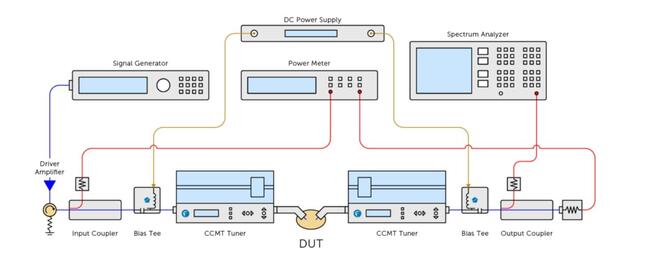
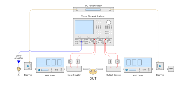
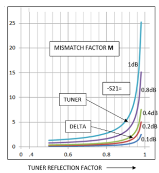
Focus recommends TRL Calibration Kits for applications such as load pull & noise parameters. Due to high reflection and low loss, tuner S-parameter measurements represent a challenge for VNA’s, because of error term determination and coupler directivity. Long experience has taught us not to rely on other calibration techniques than TRL (Thru-Reflect-Line). The popular SOLT technique is conditionally useable, but not guaranteed, up to 4GHz. The much convenient ECal method has provided questionable and inconsistent results. Our Customers are advised to be very careful with VNA calibrations, because the whole measured data depends on that.
Because of this, and to save our customers time and doubt, Focus has developed and offers a set of precise and reliable TRL calibration kits from 0.03 to 110 GHz with the following connector types: 7/16, N, APC-7, 3.5mm, 2.9mm, 2.4mm, 1.85mm, WR-15, WR-10. Our calibration kits are compatible with all commercial network analyzers.
For more information on TRL Calibration Kits, please read the following paper on TRL Versus SOLT

The automotive industry is a sector frequently on the cusp of transformation. Fast-paced industry shifts span technology innovations, regulatory standards, green initiatives, and customer expectations, influencing manufacturers’ testing needs, growth objectives, and overall business strategies. Companies striving for a competitive edge focus on sustainable practices, regulatory compliance, and innovation in Electric Vehicles (EVs), alternative fuels, and autonomous driving systems. This positions the automotive industry in vital need of testing facilities that are future-proofed for rapid and ongoing transformation.

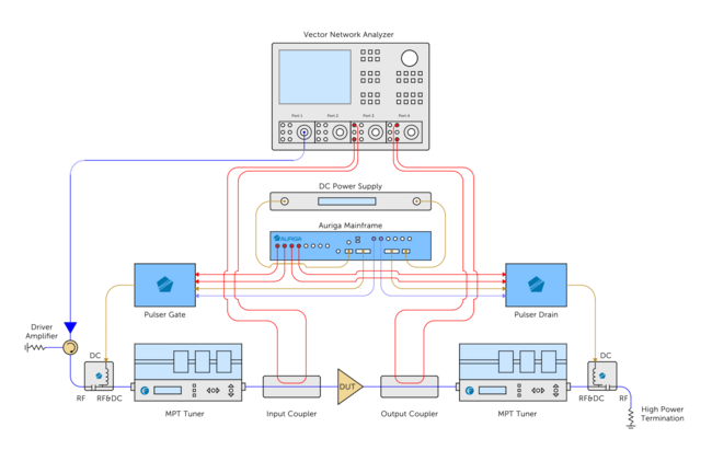
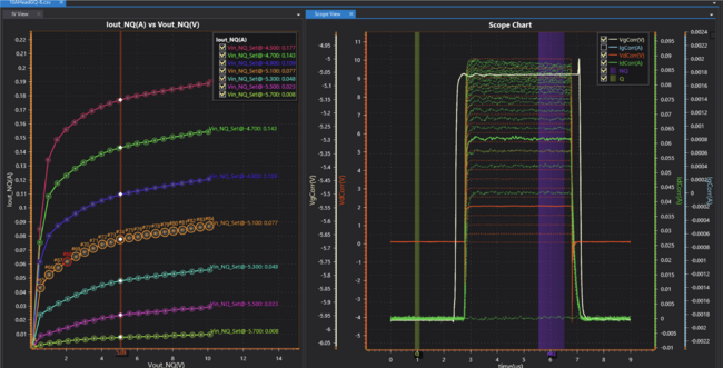
Introducing Auriga’s 5th generation pulsed IV/RF characterization system delivers unparalleled performance, capturing measurements with incredible speed and accuracy. Pulsed IV (current-voltage) measurements have emerged as the preferred method of capturing current-voltage characteristics of active devices such as field effect (FETs) and bipolar junction (BJTs) transistors. With the growing popularity of higher-power devices, like GaN HEMTs, LDMOS, SiC, and graphene, current and voltage requirements are constantly being pushed higher and higher.


-
Supports the latest 5G FR1 and IEEE 802.11ax standards
-
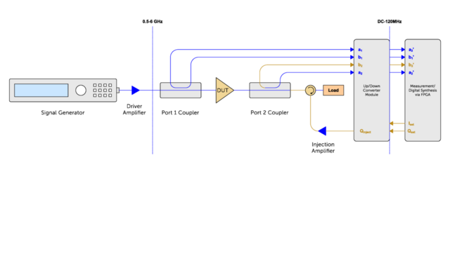
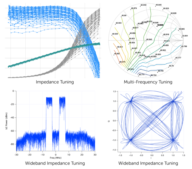
up to 1GHz active load pull bandwidth capability
-
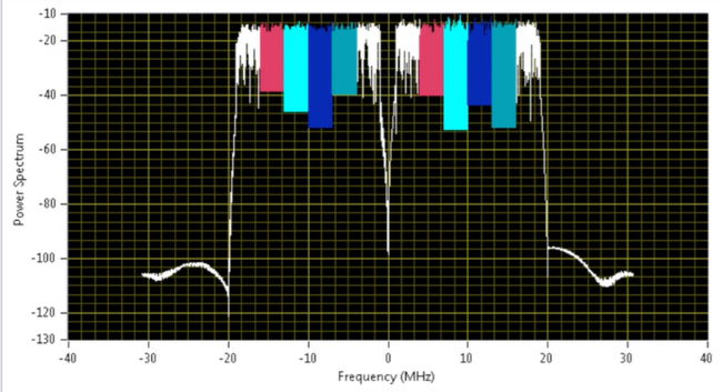
Test the latest high bandwidth and high modulation cellular standards such as 1024QAM 802.11ax
-
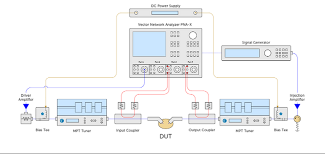
This system can be used in all parts of the design cycle
-
-
Initial device characterisation
-
MMIC or PA design
-
Design verification testing
-
Product testing in the factory
-
-
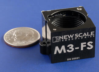
- Tiny “all-in-one” solution: no external control board needed
- Superior image quality: sub-micron lens movement with very low tilt. Now with higher dynamic stability
- Low voltage & power: 3.3 VDC input, zero power position hold
- Simple system integration: accepts high-level motion commands over standard serial interface (I2C or SPI)
- Flexible, production-ready system: compatible with M8 to M16 lenses and with typical image formats from 1/3” to 1/1.8”
- Lowest cost, fastest time to market: Fully-engineered “plug and play” solution
- Repair-focused environment for XJDeveloper / XJRunner tests.
- Full Connection test.
- RAM, Flash and other non-JTAG device tests.
- Flash, FPGA, CPLD and EEPROM programming.
- Layout Viewer* to show the physical location of faulty nets, pins and components.
- Schematic Viewer* to show the circuit design around faults.
- Direct control of the pins/balls of JTAG devices.
- View pin states graphically in real time or capture them in the Waveform Viewer.
- Trace signals to identify shorts, opens and other faults.


slide 1 of 1
