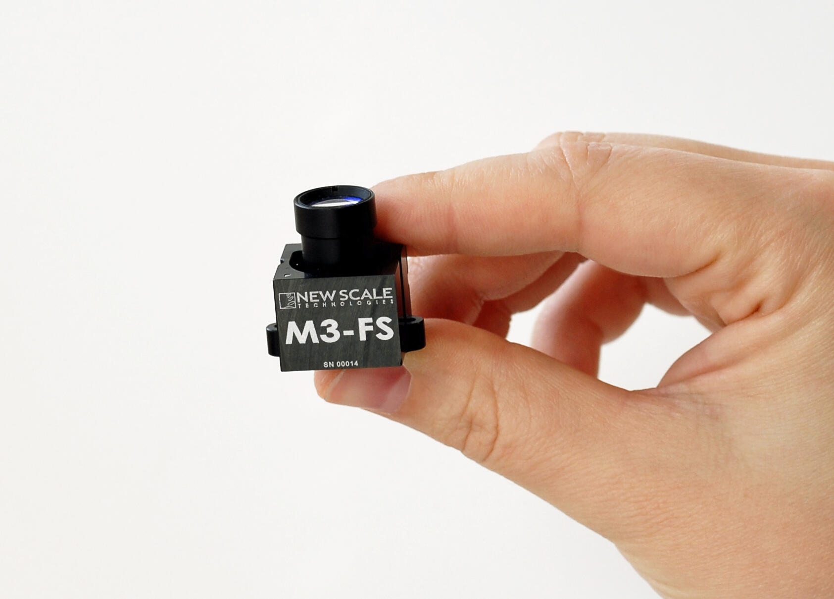
New Scale Technologies - M3-FS and M3-F Focus Modules
- Tiny “all-in-one” solution: no external control board needed
- Superior image quality: sub-micron lens movement with very low tilt. Now with higher dynamic stability
- Low voltage & power: 3.3 VDC input, zero power position hold
- Simple system integration: accepts high-level motion commands over standard serial interface (I2C or SPI)
- Flexible, production-ready system: compatible with M8 to M16 lenses and with typical image formats from 1/3” to 1/1.8”
- Lowest cost, fastest time to market: Fully-engineered “plug and play” solution
Precision lens control for highest image quality
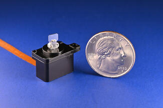
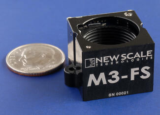
M3-F and M3-FS focus modules add high-resolution lens motion, with excellent dynamic stability, to the smallest OEM vision systems. Each module is a complete closed-loop motion solution and requires no more space than a typical fixed lens mount. Very low power is needed to move the lens and zero power is needed to hold the lens in any position, making the M3 Focus Module ideal for battery-powered devices.
All M3 smart modules have embedded closed-loop control. They need only simple high-level motion commands from the camera processor, making system integration fast, simple and cost-effective.
Precise lens position control (0.5 µm resolution) and best-in-class bi-directional repeatability enable you to capture the sharpest images in the shortest time. Designed for long life with high performance, M3 modules are not susceptible to temperature or power variations.
Improved dynamic stability and precision
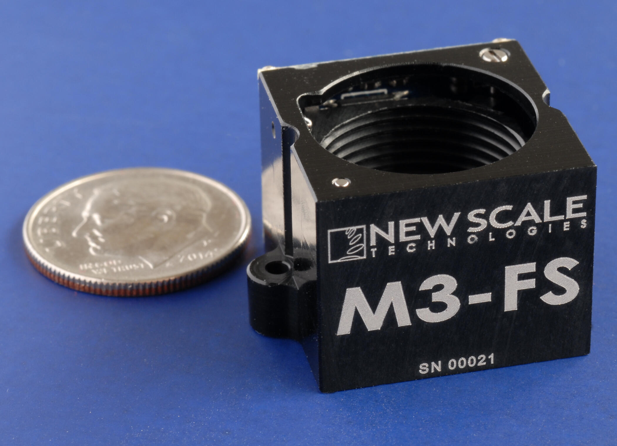
The new M3-FS focus module is a drop-in replacement for the original M3-F focus module. The aluminum structure and innovative ball bearing guide mechanism deliver a 3x improvement in tilt and accuracy. The new M3-FS features superior dynamic stability, minimizing pixel shift with changing camera orientation. This makes it ideal for miniature handheld, portable and mobile systems. Maximum lens diameter is M16.
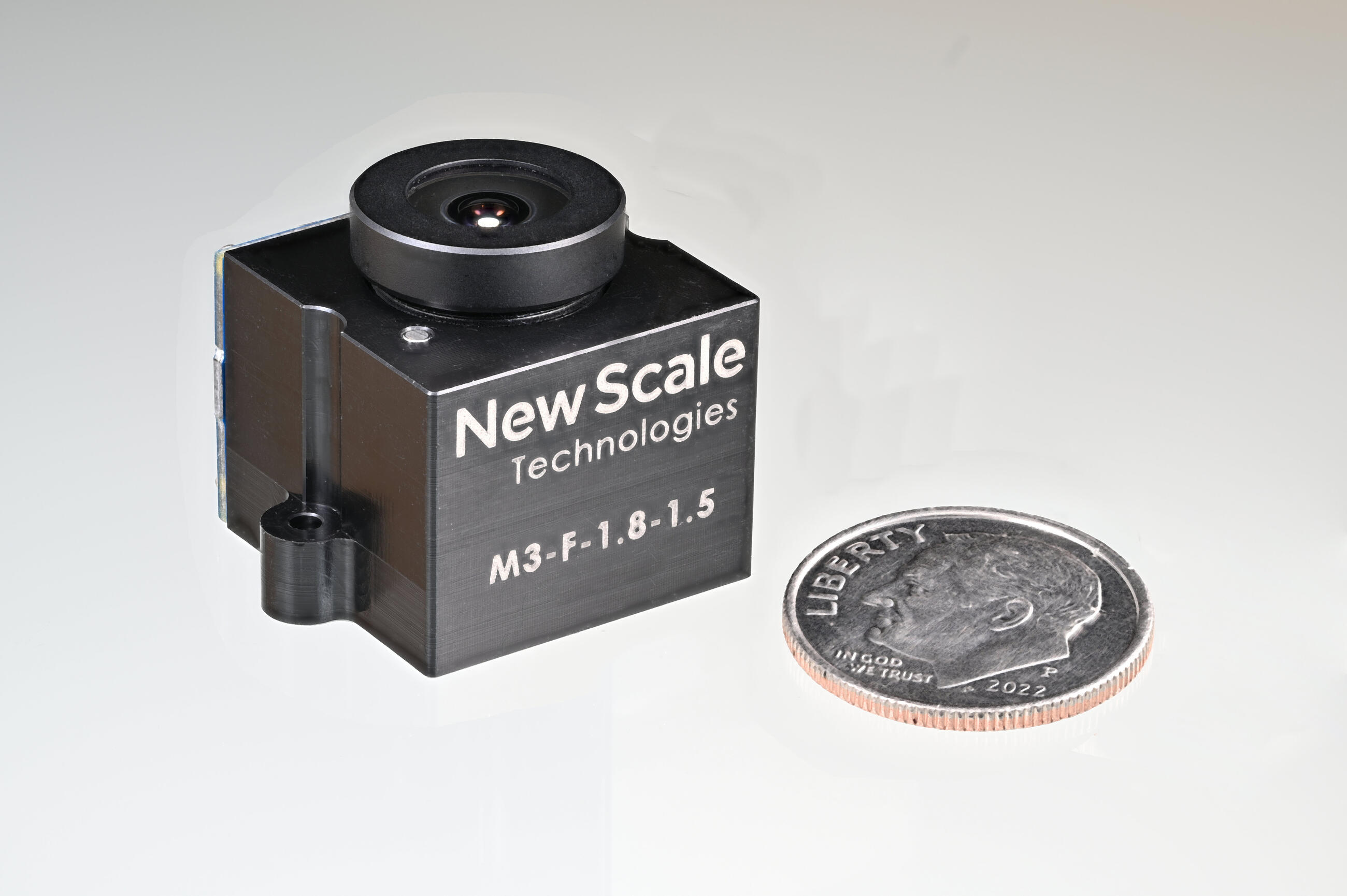
The original M3-F focus module, with machined Delrin housing and a pin-bushing guide, remains an economical choice for lower-precision requirements or fixed camera positions. Maximum lens diameter is M12.
Simple integration
Integration with camera processor
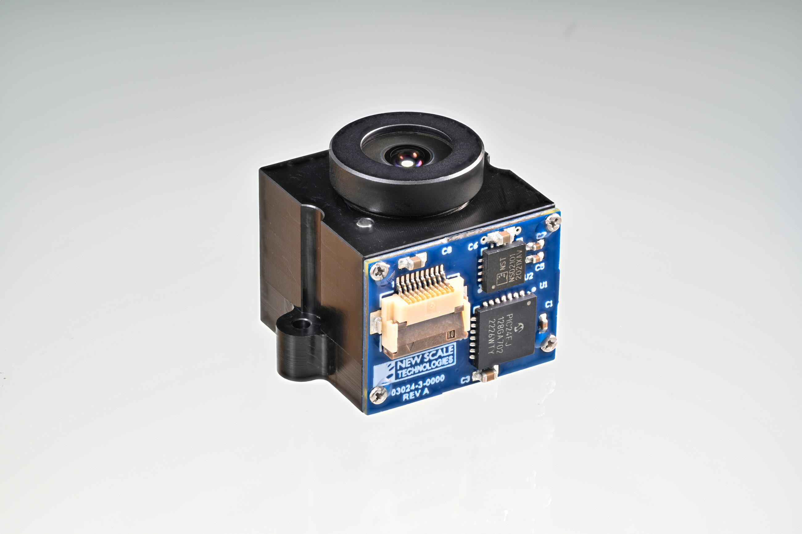
Both the M3-FS and M3-F smart focus modules feature embedded closed-loop control. You provide simple, high-level motion commands from the camera processor over a standard I2C or SPI interface.
Lens installation and alignment
Install your lens using the threaded inside diameter of the M3 module. The M3-FS accepts a maximum M16 diameter lens, or an M12 lenses with a standard adapter. Smaller lenses may be feasible depending on the optical design. The M3-F accepts a maximum M12 lens directly.
For typical camera integration, “active alignment” is required to align the optical centerline of the lens orthogonal to the image sensor by moving the M3 module and lens as a single assembly.
After alignment, the base of the module is typically secured to the image sensor board using shims, adhesive and screws. The lens back focal distance is then set by rotating the lens in the threads and securing it with a small amount of adhesive in the threads.
Refer to "Datasheets & Downloads" tab for more specifications.
Applications
High-resolution cameras for miniaturized systems and handheld, portable or mobile instruments
- In-vitro diagnostics (IVD)
- Robotic inspection
- Miniature microscopes
- Surveillance & remote sensing
- Biometric identification
- Imaging arrays
- Process control & machine vision
- Guidance, targeting & UAVs
|
Model |
M3-FS |
Original M3-F |
|---|---|---|
|
Lens Type (lens not included) |
M16x1mm Accepts M12x0.5mm with standard adapter. Other sizes by special order |
M12x0.5mm Accepts smaller lenses (to M8x0.35) with adapter by special order |
|
Lens Weight (note 1) |
< 5 grams (all orientations) |
< 5 grams |
|
Travel Range |
up to 1.5 mm |
up to 1.5 mm |
|
Housing Dimensions |
20 x 23 x 16 mm including controller |
20 x 22 x 16 mm including controller |
|
Max Image Sensor Area (image sensor not included) |
17 x 17 mm (see drawing) |
17 x 17 mm (see drawing) |
|
Max Speed |
5 mm/s |
5 mm/s |
|
Resolution |
0.5 μm |
0.5 μm |
|
Repeatability |
Uni-directional: +/- 2.5 μm Bi-directional: +/- 5 μm |
Uni-directional: +/- 8 μm Bi-directional: +/- 20 μm |
|
Linear Accuracy |
+/- 12 μm |
+/- 30 μm |
|
Static Tilt |
< +/- 0.7 degree |
< +/- 1 degree |
|
Dynamic Tilt |
< +/- 0.05 degree |
< +/- 0.15 degree |
|
Static Concentricity |
< +/- 0.25 mm |
< +/- 0.25 mm |
|
Dynamic Concentricity |
< +/- 0.002 mm typical |
< +/- 0.02 mm |
|
Digital Interface |
I2C or SPI |
I2C or SPI |
|
Input Voltage |
3.1 to 3.6 VDC |
3.1 to 3.6 VDC |
|
Input Power (note 2) |
< 1 Watt (5mm/s with 5g mass) < 0.13 Watts quiescent |
< 1 Watt (5mm/s with 5g mass) < 0.13 Watts quiescent |
|
Temperature and Humidity (note 3) |
5°C to 70°C (lower possible) < 70% relative humidity non-condensing |
5°C to 70°C (lower possible) < 70% relative humidity non-condensing |
|
Lifetime (note 4) |
> 10 million random moves while not exceeding 1.2 km total travel (See note 4) |
> 2 million cycles (fixed orientation) or 500,000 cycles (random orientation) |
|
Weight of Module (without lens) |
8 grams |
5.8 grams |
|
Compliance |
CE, RoHS |
CE, RoHS |
|
Control Interface |
Via USB adapter from PC or directly via I2C or SPI |
Via USB adapter from PC or directly via I2C or SPI |
|
Controller |
Embedded |
Embedded |
Note 1: Fixed orientation may allow for heavier lens operation. Please consult the factory.
Note 2: Power depends on input voltage, speed & load.
Note 3: Consult the factory for lower temperature requirements.
Note 4: M3-FS specification corresponds to 10 million moves with average random move of 120 µm. Lifetime depends on application and use case. Please consult factory to discuss your specific system design.
