Focus Microwaves - Sub-18GHz Tuners
More Product Information

-
High spatial resolution
-
IEEE 1588 PTP
-
Power over Ethernet
-
Defect pixel masking
-
Monochrome (GT4400) and color (GT4400C) models
-
Screw mount RJ45 Ethernet connector for secure operation in industrial environments
-
Supports cable lengths up to 100 meters (CAT-5e or CAT-6)
-
Trigger over Ethernet Action Commands allow for a single cable solution to reduce system costs
-
Comprehensive I/O functionality for simplified system integration
-
Planarity adjusted (PA) EF Lens Mount (option -18) for electronic control of aperture and autofocus
-
Easy camera mounting via standard M3 threads at all sides and 1/4-20 tripod mounting hole
-
Defect pixel masking feature with the Defect Mask Loader tool that allows you to manage a user defined defective pixel list to match your application and optimize the life cycle of the camera.
-
Easy software integration with Allied Vision's Vimba Suite and compatibility to the most popular third party image-processing libraries.


Bias tees with a perfect balance of RF performance and DC power handling
Auriga’s Bias Tees balance impressive RF performance with heavy-duty power handling across multiple frequency bands ranging from 100 MHz to 67 GHz. They are designed for rigorous usage without sacrificing RF performance. Only the highest-quality materials are used to minimize signal loss and enable efficient heat removal.
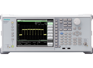
For next-generation broadband and multicarrier communication system, such as 5G mobile and broadcast satellites
- Built-in 5G measurement software supports efficient development and production
- All-in-one 5G NR/V5G (sub-6 GHz/mmWave) coverage
- High EVM performance due to wide dynamic range (EVM: <1%)
- One-button dynamic-range optimization at EVM measurement
- Multicarrier batch (all-at-once) analysis
- Amplitude/phase/timing difference measurement for each carrier
- Maximum analysis bandwidth: 1 GHz
- Excellent amplitude and phase flatness performance
- Wide dynamic range measurement: >140 dB
- Long-term capture using large memory
- With PCIe/USB3.0 connector equipped
- Transfers captured data to external PC at faster speed than 1000BASE-T

- LMR Signal Analyzers with Coverage Mapping: P25, P25 Phase 2, DMR (MotoTRBO™), TETRA, NXDN, dPMR, PTC-ITCR, PTC-ACSES, NBFM, FDD & TDD LTE
- Broadband Signal Analyzers: LTE, WiMAX
- Interference Analyzer with Interference Mapping and support for MA2700A Handheld Interference Hunter
- Auto Test and Alignment of Motorola APX P25 mobiles and portables
- Direct measurement of up to 150 watt transmitters
- Spectrum Analyzer: 9 kHz – 1.6 GHz, optional to 6 GHz
- Cable and Antenna Analyzer: 500 kHz – 1.6 GHz, optional to 6 GHz
- Return Loss, VSWR, Insertion Loss, S11 / S21, DTF
- PIM Hunting
- Internal Power Meter, optional External Power Sensor
- Handheld, battery-operated design
- Weighs less than 7.6 lb (including battery)
- Rugged, field-proven design using Anritsu's 9th generation hardware platform
- Daylight viewable color touchscreen display
- Superior Immunity to RF interference
- Remote control via Ethernet
- Standard three-year warranty (battery one-year warranty)


Introducing Auriga’s 5th generation pulsed IV/RF characterization system delivers unparalleled performance, capturing measurements with incredible speed and accuracy. Pulsed IV (current-voltage) measurements have emerged as the preferred method of capturing current-voltage characteristics of active devices such as field effect (FETs) and bipolar junction (BJTs) transistors. With the growing popularity of higher-power devices, like GaN HEMTs, LDMOS, SiC, and graphene, current and voltage requirements are constantly being pushed higher and higher.

Focus provides the deepest portfolio of wideband fundamental and harmonic passive tuners. Passive impedance tuners generate controllable reflection factor (Impedance) across the smith chart over a given frequency range. Focus uses two basic technologies:
-
From 100MHz to 120GHz we use the slide screw technique in which a reflective probe is inserted into a low loss slotted transmission line.
-
For frequencies from 10MHz to 170MHz we use a lumped element technology, whereby variable capacitors are connected with optimized lengths of coaxial cable. To view our Low Frequency Tuners, Click Here!
Most Focus Passive Tuners use long lasting RF probes which are designed for optimal tuning accuracy and are free of spurious resonances. The combination of multiple probes provide ultra wideband coverage in one single tuner. All Focus Passive Tuners are LAN controlled and include on-board impedance synthesis firmware.
For more information on Passive Tuners, visit our youtube channel!

-
Versatile temperature range for extreme environments
-
IEEE 1588 PTP
-
Power over Ethernet
-
EF lens control
-
Monochrome (GT1930L) and color (GT1930LC) models
-
GigE Vision interface with Power over Ethernet
-
Screw mount RJ45 Ethernet connector for secure operation in industrial environments
-
Supports cable lengths up to 100 meters (CAT-6 recommended)
-
The Sony IMX174 Exmor is a high sensitivity CMOS sensor
-
Trigger over Ethernet Action Commands allow for a single cable solution to reduce system costs
-
Comprehensive I/O functionality for simplified system integration
-
Planarity adjustable (PA) EF Lens Mount for electronic control of aperture and autofocus
-
Easy camera mounting via standard M3 threads at all sides and 1/4-20 tripod mounting hole
-
Easy software integration with Allied Vision's Vimba Suite and compatibility to the most popular third party image-processing libraries.


slide 1 of 1
