-
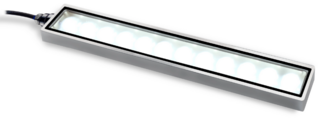
Our White High Intensity Linear Backlights offer 540 kLux output, perfect for back-lit, line-scanning applications.
-
Available in pre-engineered sizes from 6” (152mm) to 96” (2438mm) in 6″ increments.
-
A 3″ (75mm) length option is also available. Available intensity control provides illuminance adjustability for every 6″ increment via a 0 – 10v input.
-
Available in white only. For additional wavelengths please refer to our BL138 series.
Junkosha - 3 Series cables - Temperature Phase Stability
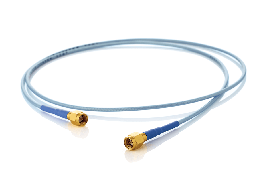
An extensive range of cables are available with a wide operating temperature range .
MWX3 series uses a porous PTFE dielectric material to ensure excellent phase stability against temperature fluctuations (continuous operational temperature range: -65 to 125°C (-30 to 85°C for MWX315)).
| Cable Type | Maximum Usable Frequencies | Standard Insertion Loss (dB/m) | Outer Cable Diameter (mm) | Cable Weight (g/m) | Continuous Operating Temperature Range (°C) | Assembly Length (mm) | ||
|---|---|---|---|---|---|---|---|---|
|
@18.5 GHz |
Maximum Frequency |
Minimum | Maximum | |||||
| MWX311 | 18.5 GHz | 3.4 | - | 2.7 | 18.5 | -65~+125 | 100 | 10000 |
| MWX312 | 2.2 | - | 4.1 | 42 | 100 | 20000 | ||
| MWX313 | 1.9 | - | 4.7 | 52 | 100 | 20000 | ||
| MWX314 | 0.8 | - | 7.7 | 125 | 200 | 20000 | ||
| MWX315 | 18.0 GHz | - | 0.76 | 8.6 | 155 | -30~+85 | 500 | 50000 |
| MWX321 | 26.5 GHz | 1.8 | 2.4 | 4.7 | 52 | -65~+125 | 100 | 20000 |
| MWX322 | 1.1 | 1.3 | 5.2 | 60 | 200 | 20000 | ||
| MWX341 | 40.0 GHz | 2.1 | 3.3 | 4 | 40 | 100 | 10000 | |
| MWX342 | 1.5 | 2.4 | 3.9 | 35 | 200 | 10000 | ||
This table provides standard length availability within our catalog. We can provide custom lengths upon request; please contact us to discuss.
Features
- Cable assembly with excellent phase stability against temperature fluctuations
- Wide temperature usage range
- We also have an extensive lineup of connectors
- Connector neck has been reinforced, providing superior durability than standard microwave cables for wiring between devices
Use
- Electronic equipment inside communication satellites and ground stations
- Electronic equipment inside flight instruments
- Air traffic control equipment
- Electronic equipment on ships
- Equipment which is severely impacted by signal leakage and interference
Bending Test Comparison Data for MWX312 and a Conventional Cable
The connector on one end of test cable (MXW312-00500AMSAMS, measuring 500 mm in length and with SMA (m) connectors on both ends) was fixed in place. The connector on the other end was moved in the sequence a → b → c, after which initial insertion loss and return loss values were compared to those after the test.
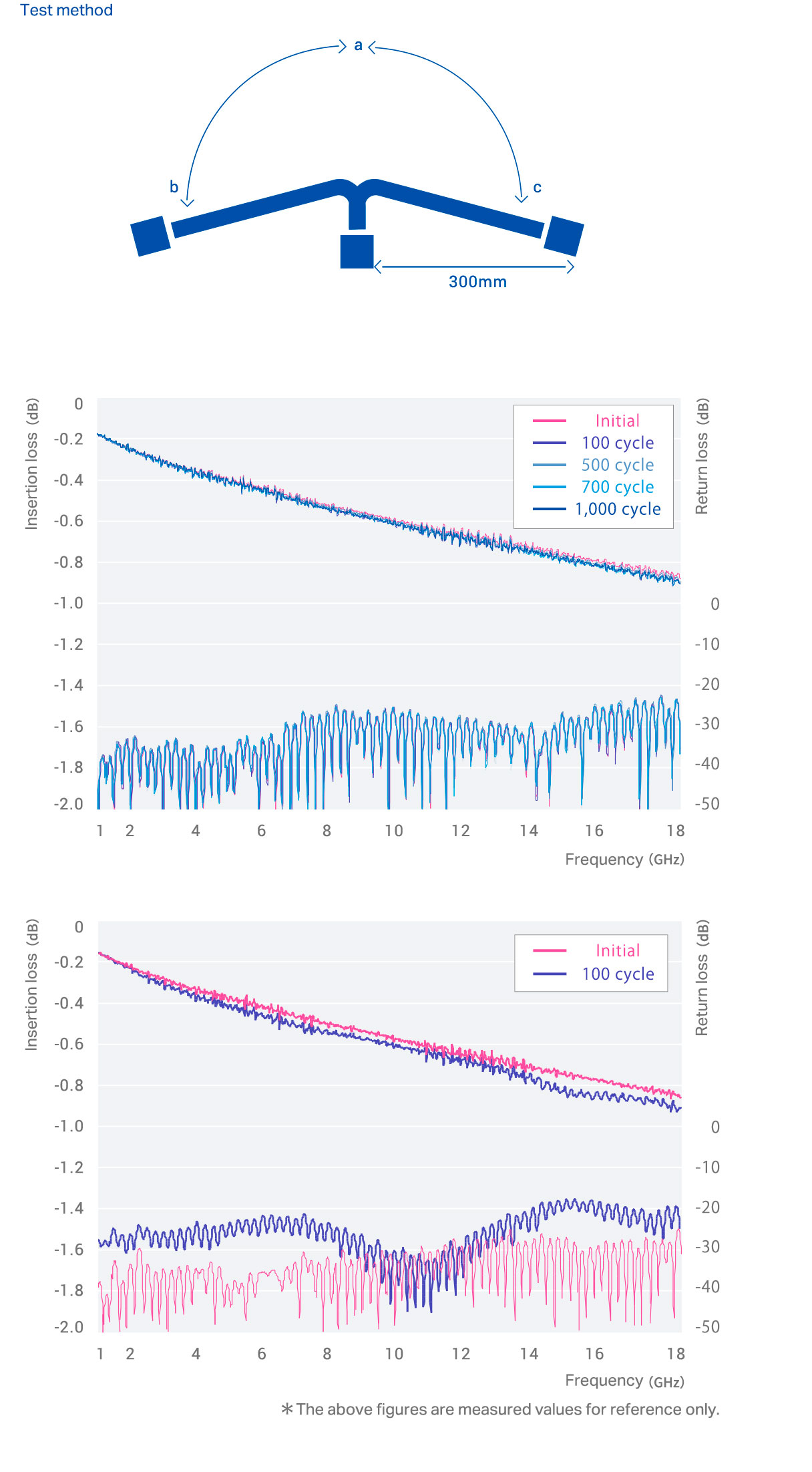
Top graph: MWX312-00500AMSAMS
Bottom graph: Conventional product
* Data are actual measurement values, not guaranteed values.
Document
More Product Information
Test & Measurement
Download Line Card
