You design the future. We help you make it happen.
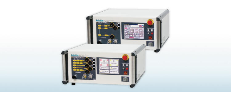
NoiseKen - Fast Transient Burst / FNS-AX4-A20/B63
- IEC 61000-4-4 Ed.3 standard compliance.
- Pre-check function is installed. Inspection before testing is now easy.
- Normal mode test support. Taking account of field troubles is possible. (option)
- Utilize an outlet box that simplifies EUT connection. (option)
- Compared with conventional products, the size has become compact. (Approximately 67% by volume)
- Easy to understand Panel display reduces mistakes in connecting power cables.
- Software control with Windows. (option)
- Next calibration date can be notified. (Windows software only)
- Employ LCD screen with multi-language support and enhanced operability.
- Maximum output voltage of 5 kV and maximum pulse frequency of 2 MHz allow you to test above the standard test level.
- CDN capacity is increased to single phase type AC 240 V 20 A, single and three phase type to AC 600 V 63 A, supporting wider range of EUT.
- Large capacity CDN (100 A or 150 A) option available for Injection test on various EUT.
- Using coupling clamps, EMS probe kits, you can test the signal lines and evaluate the noise immunity on the PCB. (option)
Electrical fast transients (EFT), such as switching transients originating from inductive load interruption, relay contact bounce, etc., are one of the main causes of equipment malfunctions. Because they can occur anywhere interfering with circuits primarily via mains and interconnection cables.
EFT is characterized by fast rise times and a short duration of pulses. Also significant is the fact that EFT comes in bursts with repetition rates exceeding 100kHz. In the real world, an EFT event is a series of pulses with changing amplitudes and repetition rates. For test purposes, the IEC 61000-4-4 standard defines an idealized EFT/B. For anyone who wants to build quality products with an extensive test program from design, qualification, production to diagnostic purpose, the FNS-AX4 simulators will serve as a critical tool with a new level of performance and efficiency meeting and far exceeding the IEC standard requirements.
Output Waveform
![]()
PULSE OUT connector waveform:50Ω
![]()
EUT LINE OUTPUT waveform:50Ω
![]()
Repetitive pulses output as burst
Specification
Generator Specification
|
Parameter |
Specification / Function |
|---|---|
|
Output Voltage |
200 to 5000 V 10 V Step |
|
Polarity |
Positive or negative, polarity alternation possible per burst |
|
Repetition Frequency |
0.1 kHz to 2000 kHz 0.1 kHz to 1 kHz / 0.01 kHz step Tolerance ± 5%, 1.0 kHz to 10 kHz / 0.1 kHz step Tolerance ± 5% 10 kHz to 100 kHz / 1 kHz step Tolerance ± 5%, 100 kHz to 1000 kHz / 10 kHz step Tolerance ± 5% 1000 kHz to 2000 kHz / 100 kHz step Tolerance ± 10%, (Limitation per voltage levels when continuous output) |
|
Number of Pulses |
1 to 1000 at a step of 1 pulse , Setting limit: 1 pulse per ms in a burst (repetition frequency 1 kHz or more) |
|
Burst Duration |
Formula for Burst duration = Pulse number / Repetition Frequency Scope of manually setting value for burst duration: 0.01 to 999 ms |
|
Burst Period |
10 to 1000ms ± 10% 10ms steps (500ms or more for polarity alternate mode) |
|
Polarity Alternate Function |
Output polarity alternated between positive and negative at each burst period Setting condition: the burst period is 500ms or more and the burst pause period [(burst period) - (burst duration)] is 100ms or more Maximum test time: 10 minutes |
|
Continuous Pulse Output |
Up to 1000 V -10 kHz or less, to 2000 V -4 kHz or less, to 5000 V -1 kHz or less. Maximum test time for each case: 10 min |
|
Frequency Modulation |
Frequency is shifted continuously between set frequency and approximately -10% from the set frequency. The modulating wave is triangular wave of approximately 20Hz |
|
External Trigger |
External trigger input invokes 1 burst output in synchronization with the trigger input. Trigger specification: Hi (+ 5V) → Lo (0 V) triggers one burst period. |
|
Pulse Waveform (at 50 Ω load) |
Pulse peak voltage: (set voltage / 2) ± 10% Rise time: 5 ns ± 30% Pulse width: 50 ns ± 30% |
|
Pulse Waveform (at 1 kΩ load) |
Pulse peak voltage: (set voltage × 0.95) ± 20% Rise time: 5 ns ± 30% Pulse width: 35 to 150 ns |
|
DC Blocking Capacitor |
10nF ± 20% |
CDC Specification
|
Parameter |
Specification / Function |
|---|---|
|
Power Capacity |
A 20 model: Single phase AC 240 V / 20 A, DC 125 V / 20 A (10 A for PE) B 63 model: three-phase AC 600 V / 63 A, DC 125 V / 63 A (10 A for N / PE) |
|
Applied Phase |
A20 model: L / N / PE B63 model: L1 / L2 / L3 / N / PE Single line or all lines can be specified individually for each phase |
|
Injection Mode |
Common mode (Normal mode available using option) |
|
EUT Line Input/Output |
φ6 mm safety socket |
|
Coupling capacitor |
33 nF |
|
Output Waveform Specification |
Pulse peak voltage: (set voltage) / 2 ± 10% Rise time: 5.5 ns ± 1.5 ns Pulse width: 45 ns ± 15 ns Set voltage ± 4000 V, frequency specified from 5 kHz to 100 kHz |
|
Input Residual Voltage |
10% or less of setting pulse voltage EUT line input is 50 Ω termination, line output is defined as open |
|
AC Line Sync |
Synchronous and asynchronous setting available. Setting phase angle: 0 to 360 ° ± 10 ° 1 °Step Synchronizable voltage: AC 85 V to rated voltage Reference phase: between L-N (A20 model), L1-L2 (B63 model) |
Other Specification
|
Parameter |
Specification / Function |
|---|---|
|
Emergency Stop |
Push lock type switch (Test stop, EUT line OFF) |
|
EUT FAIL Function |
FAIL signal from external (Hi → Lo) detected during test FAIL signal specifications VLO: 0 V, VHI: + 5 V Choose operation from test stop / pause when triggered 3 channels available for the FAIL input |
|
External Interface |
REMOTE (For external PC control), CDN I/F (For external CDN), INDICATOR (For Warning Lamp or indicator lamp) EUT FAIL INPUT (For temporary pause at EUT failure event) |
|
Accessories |
Power Cable, SG Cable, Line Input Cable, Output Cable, Waveform Check Connector, Coaxial Cable, Operation Manual, Accessory bag |
|
Operating Environment |
Temperature 15 to 35 °C Relative humidity 25 to 75% |
|
External Dimensions / Weight |
(W)430 × (H)199 × (D)370 mm (excluding protrusions) / Approximately 14 kg (A20 model) and 22 kg (B63 model) |
|
Power Supply |
AC 100 to 240 V ± 10% 50/60 Hz approx. 120 VA |
1. Polarity Reverse Function
Enables to switch for putting the positive pulse and negative one out per the one burst so as to enrich the test.
![]()
2. Pulse continuous output / Frequency modulation function
Enables to switch for putting the positive pulse and negative one out per the one burst so as to enrich the test.
![]()
TEST SETUP
![]()
Test Method using Fast Transient / Burst Simulator
- Place the simulator onto the ground place which is connected to the protective earth and connect SG terminal on the front panel to the ground plane.
- Connect power cable (Standard accessory) to AC IN on the back of the simulator.
- Place coupling adaptor CA-805B (Option) onto the ground place and connect G terminal on side connector part of the clamp to the ground plane.
- Connect PULSE OUT connector on the front of the simulator to connector of the adaptor.(Fully pay attention to that any high voltage must not be put out during the connection)
- Thread cable to be tested through the adaptor.
- Set the test conditions like the coupling voltage, etc on the touch-panel on the front of the simulator and start the test.
More Product Information
- The Direct PC bus access data acquisition system provides the required sampling rate and resolution to meet IEC 61000-4-7 measurement requirements and supports high-speed data transfers.
- PC-based Harmonic and Flicker test software provides real-time full-color data display updates and continuous PASS/FAIL monitoring.
- Automatic calculation of the maximum permissible system impedance Zsys, using the Zref and measured Flicker parameters, as required per EN/IEC 61000-3-11.
- Intuitive operating software provides IEC test setup, data analysis, display, with test reports in and MS Word format.
- High resolution, no gap acquisition data storage to ensure that all data can be streamed to disk (in ASCII format if needed) for later review and replay of the actual test.
- Single Step and Fast playback mode of test results.
- Automated Absolute and Additive (Residual) Measurements
- Real Time Cross Correlation
- Only analyzer available that allows actual noise floor measurement
- Unparalleled analog performance
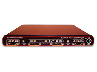
- Repeatable data
The HA7162C Real Time Phase Noise Analyzer is the industry leader with respect to proven accuracy, high reliability, automation and flexibility; offering extremely fast measurement speeds to reduce product development time and/or optimize ATE manufacturing throughput.
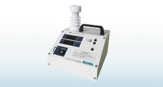
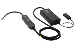
The ESD voltage meter MODEL: 18-00086B is a device that can measure the voltageholding time (holding voltage after 5 seconds) and output
specifications during the air discharge test in IEC 61000-4-2.The measured voltage is displayed on a 7-segment LED with peak and holding voltage values.
- Easily measure the Hold Time, the tester specification for air-discharge testing.
- Measure the output voltage from ±2kV to 30kV.
- Monitor the measured voltage waveform by connecting to an oscilloscope.
- Compact, lightweight and easy to carry.
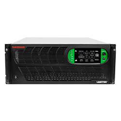
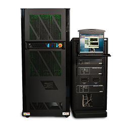
- Complete solution - battery test, simulation & solar array simulator software included
- Highest power density up to 37 kW in 4U rack height (9.25 kW/U)
- Fastest and cleanest power available (fastest transient response and low output ripple and noise)
- Universal 3-Phase AC Input accepts 180 VAC to 528 VAC
- Longest manufacturer-based reliability guarantee: 5-year warranty
- Parallel system power up to 1.2 MW
- Output voltage up to 2,000 V
- Bidirectional output current up to ±150 A, up to ±4,800 A in parallel
- True extended wide-range autoranging output
- Regenerative to 95%
- Color touch panel user interface
- Seamless transition between source and sink
- Built-in islanding detection
- Comprehensive Test Solutions - Our CTS 4.0 Series offers complete test solutions for emissions and immunity compliance testing of AC and DC power products, ensuring your products are ready for global markets.
- Single & Three Phase Operation - Offers flexibility
- Direct PC Bus Access - Provides high sampling rate and resolution for accurate measurements and high-speed data transfers
- PC-Based Harmonic & Flicker Testing - Provides real-time full-color data display updates and continuous PASS/FAIL monitoring
- Supports Global Standards - Supports European and Japanese standards
- Easy To Use Interface - Provides IEC test setup, data analysis, display, MS Word test reports, and data files generated in MS Excel format
- High Resolution - Data storage to disk for post-acquisition analysis and reporting
- Single Step - Single Step and Fast Forward replay of recorded test data at 200 mSec
- Ideal for GaN and SiC devices
- Highest system accuracy
- Fastest rise time
- High CMRR - 160 dB
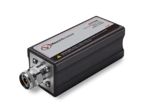
The overall performance of a power meter dependents on the power sensor employed. Maury has a variety of quality power sensors to meet virtually all applications. Maury has a complete line of Peak and Average power sensors up to 40 GHz for all of your fast rise time, wide bandwidth and wide dynamic range applications. In this document, browse through our large variety of advanced sensor solutions.

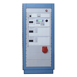
Simulator to reproduce various transient surge phenomena which are generated in a vehicle and required in the international standard ISO-7637-2 (2004) Standard, and evaluate the immune resistibility of the equipped electronics devices against the surge.
- ISO 7637-2 (2004) Standard compliant simulator
- Correspondent to the test for 12V/24V/42V systems in a vehicle
- Stand-alone usage per the each generator unit possible as well as the comprehensive control
- Large capacity CDN (60V/50A) available (Option)
- Up to 200A power supply possible (Option)
- Windows in Japanese applicable for the software program as well
Private standards or specifications by manufactures can be responded upon request.
AI, cloud computing, and hyperscalers are accelerating the demand for ultra-high-speed, low-latency connectivity, taking us past Gigabit Ethernet and into the era of Terabit Ethernet.
Teledyne LeCroy’s Terabit Ethernet solutions are engineered to help you take full advantage of this new technology cycle. The Xena Ethernet Test Platform gives developers of semiconductor, NEMs, and hyperscalers the solutions they need to validate next-gen silicon, network devices, and interconnects with confidence.
From Layer 1 signal integrity and Layer 2 traffic generation and analysis, we have the solutions you need to simulate, stress, and certify real-world performance. Support for 224Gbps electrical lanes, advanced FEC, and PCS diagnostics ensure readiness for tomorrow’s networks. Compact, desktop-friendly hardware combined with intuitive software and powerful automation ensure seamless lab-to-production workflows.
Whether you’re path-finding 1.6T or optimizing 800G deployments, Xena can fast-track your innovation cycle. Test smarter, deploy faster and reap the rewards.
NoiseKen
For over 40 years from its foundation in 1975, Noise Laboratory has been focusing on immunity test equipment and related solutions.
Now their product lines include various types of immunity test equipment ranging from those conforming to IEC 61000-4 series standards, other international or national immunity standards and even to customer's in-house test standards.
Contact Details
Shinyei Corporation of America Head Office - Sole Authorized distributor of NoiseKen products