You design the future. We help you make it happen.
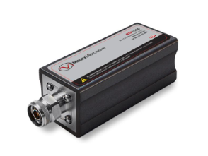
Maury MW - Peak Power Sensors Series
The overall performance of a power meter dependents on the power sensor employed. Maury has a variety of quality power sensors to meet virtually all applications. Maury has a complete line of Peak and Average power sensors up to 40 GHz for all of your fast rise time, wide bandwidth and wide dynamic range applications. In this document, browse through our large variety of advanced sensor solutions.
More Product Information

-
15’ Flexible Power Cord
-
IEC C13 / C14 Connectors
Test Tap:
-
3ft.
-
(2) fork terminals (current)
-
(1) fork terminals (ground)
-
(2) Shielded Banana (voltage)
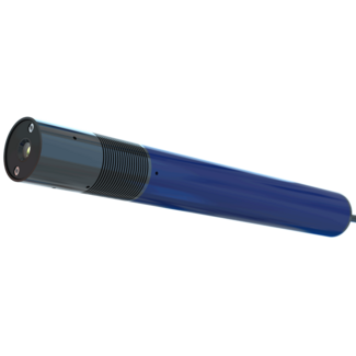
- Green laser for extra long lines and best visibility
- Optical output power up to 40mW/532nm
- Adjustable focus
- Large cooling surface for optimal heat dissipation
- Integrated power supply with high immunity to interference
- Dimensions: Ø 40mm x 329mm
The ZRG-F Module is a diode-pumped solid-state (DPSS) laser that emits bright green light at a wavelength of 532 nm. It delivers exceptionally bright, long laser lines, setting the standard for applications such as sawmills, textile cutting tables, and natural stone processing. With its rugged construction and integrated wide-range power supply, it is ready to connect and immediately operational. The focusable line laser is available in four power classes from 5 mW to 40 mW, ensuring maximum flexibility for different application needs. When visibility and precision matter most, the ZRG-F is the number one choice.

- Our EuroBrite™ lineup outdoes the competition in so many ways. With more features at a competitive price point, there’s no better value in machine vision lighting:
- Complete built-in control for continuous and strobe modes.
- Adaptive Power™, a feature of the EuroBrite™ lighting controller, utilizes an onboard thermistor to maximize light output in continuous mode.
- Adaptive Overdrive,™ another feature of the EuroBrite™ lighting controller, provides a maximal output pulse in strobe mode regardless of the exposure period.
- IP67 sealed enclosure suitable for washdown environments.
- Rugged construction that has been tested to withstand over 1000lb.
- Industrial grade LEDs providing high-intensity illumination of 85klux (working distance of 100mm).
- Daisy chain up to 4 for a combined length of 24”.
- Designed for Orbit-Topping and Station Keeping
- 40% Weight Saving Convention Propulsion
- Excellent Thrust-to-Electrical Power Ratio

- The RL4260 is characterized as a Medium Aimed Bright Field ring light.
- Precisely aimed LEDs provide a level of lighting control not found in traditional illuminators.
- A range of standoffs and fields of view may be specified at the time of order.
- The ring light is available in a wide range of wavelengths from UV to IR, including a 3 channel RGB version.
- Diffuser and polarizer options are also available.
- The large inner diameter of the ring light can accommodate lenses up to 55mm in diameter.
- The light can also be ordered with an optional mounting ring.
")
NoiseKen simulators to reproduce fast rise-up noises which are generated when switching ON / OFF electric current on the inductive load.
Since the pulse includes broadband frequency and its rise-up time is fast at 3ns or less, it can make the noise coupling dense and effective to reproduce the malfunctions of electronics equipment under the test.
It can realize performance evaluation of electronics equipment's upon reproduction of line noises which are intruded to the power supply lines or induced noises onto the telecommunication lines.
Specially modified design allows:
- Air to water heat exchanger added to system
- True current source
- Fast transient response
- Little to no current overshoot
- Low stored energy

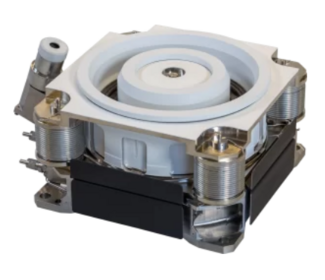
- Combine up to 12 fail-safe building blocks, dual SPDT, SP4T, SP6T, or transfer switch in a compact 1U footprint
- Front “pluggable” relays facilitate field maintenance
- Embedded web interface provides interactive utility to monitor and control relays from anywhere in the world
- Flexible API supports IVI and Linux development environments minimizing software investment
- LXI Trigger Event implementation provides seamless test synchronization with external devices
- Store up to 128 relay state configurations for quick recall, including an automatic power up state
- Define exclude lists to avoid setting an undesirable configuration
- Relay odometer tracks closures to facilitate preventative maintenance
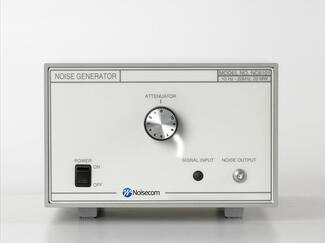
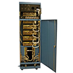
- Additive white Gaussian noise
- Integrated amplifier
- Manual attenuator
- NC6000A -BER testing, and SNR applications
- NC8000A – Secure signal jamming
- Military Applications
- Custom configurations available (consult factory)
The NC6000A and NC8000A Series instruments are designed for general-purpose noise applications on the bench, or in a rack test station. The manual controls make it simple to operate and reduce test set up time. Standard units can be modified for specific customer requirements. Please consult the factory for pricing and availability of these requests.
Maury Microwave
Website
Maury Microwave is a pioneering leader in the design and manufacture of precision RF and Microwave calibration, test & measurement, and modeling solutions that are powering global efforts toward a more secure, more connected, future.
Maury Microwave offers Measurement and Modeling Device Characterization Systems and Services including nonlinear passive, active and hybrid-active fundamental and harmonic load pull, non-50Ω X-Parameter modeling, pulsed IV Pulsed s-parameters and compact transistor modeling, and patent-pending ultra-fast/accurate noise parameters.