You design the future. We help you make it happen.
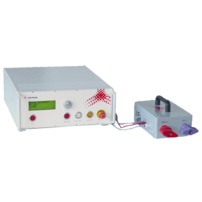
NoiseKen - Lightning Surge Simulator (IEC 61000-4-5 Ed.3, IEC 61000-4-12 Ed.3)
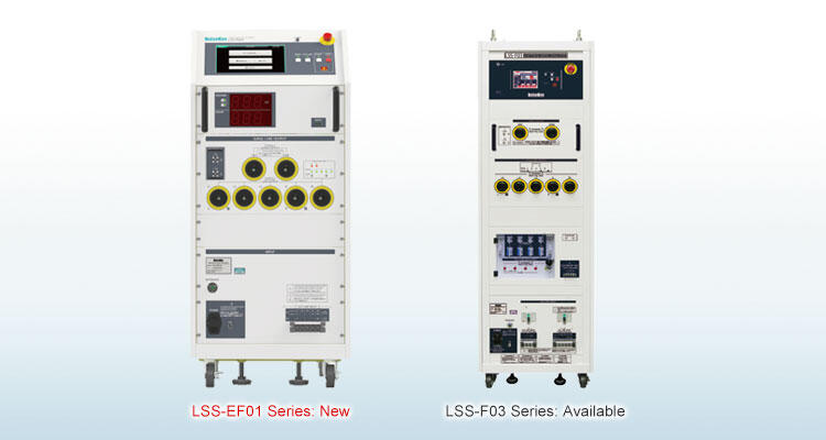
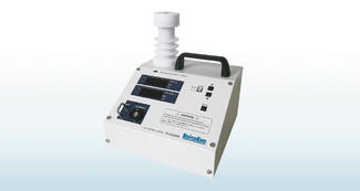
LSS-EF01 series
This simulator evaluates the immunity of electronic equipment by simulating "highenergy induced lightning noise" induced in power distribution lines and communication lines due to fluctuations in the earth's potential caused by lightning strikes. This is an entry model of the LSS-F03 series. (Maximum output voltage 6kV)
LSS-F03 series
A tester simulatively generates "High energy induced lightning noise" which induced to distribution lines or communication lines by ground potential fluctuation caused by lightning strikes.
LSS-EF01 series
- Test equipment compliant with IEC 61000-4-5 Ed.3, IEC 61000-4-12 Ringwave standards.
- Maximum output voltage 6kV
- Large-screen operation panel with 10.1" LCD module for improved visibility and operability.
- Designed for smooth operation whether sitting or standing.
- Equipped with a display panel that allows the user to instantly grasp the test status (voltage and number of times applied) even from a distance.
- Uses a reliable output connector inherited from the LSS-F series.
- Connection cable settings are indicated by LED lamps.
- Can be combined with high-capacity external CDN (custom).
- PC software support allows for operation from a PC.
- Daily inspections can be easily performed using the pre-check software (optional).
LSS-F03 series
- Lightning surge simulator compliant with the IEC61000-4-5 Edition 3 requirements
- Maximum output voltage 15 kV (maximum coupling of 15 kV to AC / DC CDN and 6 kV to Telecom CDN) Enables to conduct the more extended reliability test including the destructive test
- Large size LCD for the operation is adopted for realizing better visibility and operatability
- Easy operation for the sequential tests with adoption of MPU control Surge output / Waveform switching / Polarity switching / Sequence can be automated sequentially
- Selectable either MANUAL or PROGRAM mode MANUAL mode is used for the test according to the Standard or performing single conditioned test and PROGRAM mode can perform different conditioned tests sequentially so that the tests can be performed easily along purposes.
- Excellent safety with equipment of interlock
- Standard equipment of terminal for checking the waveforms:Enable to check the waveforms in connection to an oscilloscope on hand with BNC cable
- Isolation transformers in line-up (Option)
- In order to avoid resonance with the power supply, possible to vary the constant of the decoupling network (1.5, 1.3, 1.0, 0.8 mH)(Customized production). When some products like a power conditioner for photovoltaic application are connected to a lightning surge simulator, the resonant phenomena may occur and the products may not work well. In LSS-F03 series (with customization), possible to change constants of the inductances so as to avoid such problem
Surge generator
|
Parameters |
Functions & Performance |
Remarks |
|
|---|---|---|---|
|
1.2/50μs-8/20μs Combination waveform |
Open circuit voltage |
0.5kV ~ 6.6kV ±10% |
Cable length: 0.5 m (one side) Voltage step: 0.00kV-2.00kV: 0.01kV step 2.1kV-6.6kV: 0.1kV step Settings can be made from 0kV |
| Front time |
1.2μs±30% |
||
|
Duration |
50μs±20% |
||
|
Short-circuit current |
250A ~ 3300A ±10% |
||
|
Front time |
8μs ±20% |
||
|
Duration |
20μs ±20% |
||
|
0.5μs-100kHz Ring waveform |
Open circuit voltage |
0.25kV ~ 6.6kV ±10% |
Cable length: 0.5 m (one side) Voltage step: 0.00kV-2.00kV: 0.01kV step 2.1kV-6.6kV: 0.1kV step Settings can be made from 0kV |
| Front time |
0.5μs±30% |
||
|
Frequency |
100kHz±10% |
||
| Attenuation value |
2ndpeak:40% < 1st < 110% 3rdpeak:40% < 2nd < 80% 4thpeak:40% < 3rd < 80% |
||
| Short-circuit current |
(Set voltage/12Ω) ±10 (Set voltage/30Ω) ±10 |
||
|
Front time |
0.2μs ~ 1μs |
||
|
Output polarity |
Positive/Negative |
||
|
Surge generation circuit type |
Floating | ||
|
Minimum charge time |
0.0kV-4.0kV: 5 sec. 4.1kV-6.6kV: 10 sec. |
1.2μs/50μs-8/20μs Combination waveform |
|
| 0.0kV-6.6kV: 5 sec. |
Ring waveform |
||
*1: Check with input voltage AC200V, resistive load 10Ω, and resistive load 4Ω.
AC/DC CDN
|
Parameters |
Functions & Performance |
Remarks |
|
|---|---|---|---|
|
Superimposed surge waveform |
1.2/50μs-8/20μs combination waveform Ring waveform |
||
|
1.2/50μs-8/20μs Combination waveform |
Open circuit voltage |
0.5kV~6.6kV ±10% |
Coupling circuit: 18μF Decoupling coil: 1.5mH Cable length: 0.5m on each side Setting is possible from 0kV Line input side open |
|
Front time |
1.2μs±30% |
||
|
Duration |
50μs+10μs /-10μs |
||
|
Short-circuit current |
250A~3300A ±10% |
||
|
Front time |
8μs±20% |
||
|
Duration |
20μs±20% |
||
| Injection mode |
Line-to-Line |
Coupling circuit: 18 μF (10 Ω + 9 μF selectable) |
|
|
Between Line and PE |
Coupling circuit: 10Ω + 9μF (18μF selectable) |
||
| Open circuit voltage |
0.5kV~6.6kV ±10% |
Coupling circuit: 10Ω + 9μF Decoupling coil: 1.5mH Cable length: 0.5m on each side Setting is possible from 0kV Line input side open |
|
| Front time |
1.2μs±30% |
||
|
Duration |
50μs+10μs /-25μs |
||
|
Short-circuit current |
41.7A~550A ±10% |
||
| Front time |
2.5μs±30% |
||
|
Duration |
25μs±30% |
||
| Injection mode |
Line-to-Line |
Coupling circuit (Line-to-Line): 18 μF (10 Ω + 9 μF selectable) |
|
|
Between Line and PE |
Coupling circuit (Line-PE): 10Ω + 9μF (18μF selectable) |
||
|
0.5μs-100kHz Ring waveform |
Open circuit voltage |
0.25kV~6.6kV ±10% |
Coupling circuit: 4.5 μF Decoupling coil: 1.5mH Cable length: 0.5m on each side Setting is possible from 0kV Line input side open (excluding simultaneous injection settings) |
|
Front time |
0.5μs±30% |
||
|
Frequency |
100kHz±10% |
||
|
Attenuation value |
2ndpeak : 40% < 1st <110% |
||
|
3rdpeak:40% < 2nd < 80% |
|||
|
4thpeak:40% < 3rd < 80% |
|||
| Short-circuit current |
(Set voltage / 12Ω) ±10 |
||
| Front time |
0.2μs~1μs |
||
|
Injection mode |
Line-to-Line Between Line and PE |
Coupling circuit: 4.5 μF (10Ω used in CW cannot be inserted) |
|
|
Simultaneous injection |
Coupling circuit: 4.5 μF for each line |
||
*1: Check with input voltage AC200V, resistive load 10Ω, and resistive load 4Ω.
Control Specifications
|
Parameters |
Functions & Performance |
Remarks |
|---|---|---|
|
Discharge interval |
5 sec - 999 sec (depending on the set voltage) |
1.2/50μs waveform |
| 5 sec - 999 sec (depending on the set voltage) |
Ring waveform |
|
|
Discharge count |
1 to 999 times / 1 time step |
|
|
Trigger Input |
Asynchronous |
Depending on the repetition time |
|
AC line sync 0° - 360° / 1° step |
When AC superimposed |
|
|
Save Settings |
Test settings can be named (title name) and saved in internal memory |
|
|
STANDARD mode |
Preset settings regulated by the IEC61000-4-5 standard |
Normal mode - common mode automatic transfer |
|
Communication Function |
RS-232 compliant optical communication |
Other specifications
General Specifications
|
Power supply |
AC100V~AC240V ±10% 50Hz / 60Hz |
|
|---|---|---|
|
Operating environment |
Temperature: 15 - 35° C Relative humidity: 25 - 75%. |
|
|
Dimensions |
W500 × H1140 × D600 mm |
(excluding protrusions) |
|
Weight |
Weight |
|
Safety Specifications
|
Emergency Stop |
Push-lock push button switch Test stop, High voltage OFF, EUT Line OFF |
EUT Line OFF is selectable |
|---|---|---|
|
Interlock function |
Surge output connector status detection, connector status detection for externally connected device | |
|
Warning lamp display |
LED blinks red when the test starts. |
|
|
Warning lamp connector |
Equipped with a connector to connect a warning lamp. Warning lamp lights on at test start. |
|
Output monitor function
|
Voltage Monitor |
BNC output, 2000V/V Output accuracy: ±10% of the actual output ratio (±15% of the ratio of actual output in ring waveform) |
Surge out settings *2 When output is open No waveform guarantee |
|---|---|---|
|
Current Monitor |
BNC output, 1000A/V Output accuracy: ±10% of the actual output ratio (±15% of the ratio of actual output in ring waveform) |
Surge out settings *2 When output is short-circuit No waveform guarantee |
Model
|
Model |
Output Waveform |
CDN |
Dimensions |
Weight |
|---|---|---|---|---|
|
LSS-FE01A1 |
1.2/50μs-8/20μs Combination waveform |
AC Single phase / DC |
W500 x D600 x H1140 [mm] |
130kg |
|
LSS-FE01A3 |
AC single-phase and three-phase/DC |
155kg |
||
|
LSS-FE01B1 |
1.2/50μs-8/20μs Combination waveform 0.5μs -100kHz Ring waveform |
AC Single phase / DC |
135kg |
Standard Accessories
|
Name |
Quantity |
Remarks |
|---|---|---|
|
AC cable |
1 pc. |
|
|
Surge output cable |
2 pcs. |
crocodile clip |
|
Line output cable |
3 pcs. |
Single phase (A1/B1) type |
|
5 pcs. |
Three-phase (A3) type |
|
|
FG cable (2m) MODEL: 05-00070A |
1 pc. |
M6 Round - M6 Round |
|
Coaxial monitor cable (1m) MODEL: 02-00128A |
1 pc. |
BNC−BNC |
|
Interlock connector |
1 pc. |
|
|
Hi-voltage connector cap (MODEL: 05-00060A) |
5 pcs. |
Single phase (A1/B1) type |
|
7 pcs. |
Three-phase (A3) type |
|
|
Accessories bag |
1 pc. | |
|
User's Manual |
1 copy |
LSS-F03 Series
Specifications
|
Parameter |
Specification |
Note |
|---|---|---|
|
Surge generating unit |
||
|
1.2/50μs - 8/20μs Combination waveforms |
Output voltage 0.5 kV ~ 15 kV ± 10% | |
|
Front time 1.2μs ± 30% |
Common for all models Voltage step : 0.1 kV step The setting can be from 0 kV |
|
|
Duration 50μs ± 20% |
||
|
Output current 250 A ~ 7500 A ± 10% |
||
|
Front time 8μs ± 20% |
||
|
Duration 20μs ± 20% |
||
|
10/700μs-5/320μs Combination waveforms |
Output voltage 0.5 kV ~ 15kV ± 10% | |
|
Front time 10μs ± 30% |
Models:C1A / C3A Voltage step : 0.1 kV step The setting can be from 0 kV |
|
| Duration 700μs ± 20% | ||
| Output current 12.5 A ~ 375 A ± 10% | ||
|
Front time 5μs ± 20% |
||
|
Duration 320μs ± 20% |
||
|
Output polarity |
Positive / Negative | |
|
Interval |
10 sec. ~ 999 sec., depending on the set voltage |
10 sec. ( < 6 kV) 15 sec. ~ in 10/700μs waveform |
|
Output impedance |
2 Ω ± 10% |
1.2/50μs waveform |
| 40 Ω ± 10% |
10/700μs waveform |
AC/DC CDN
|
Coupling surge waveform |
1.2/50μs - 8/20μs combination waveforms |
|
|---|---|---|
|
Max. coupling surge voltage / current |
Up to the values which can be set | |
|
Coupling network Correspondent to IEC61000-4-5 |
18 μF |
Between LINE - LINE (10 Ω + 9 μF selectable) |
|
10 Ω ± 9 μF |
Between LINE - PE (18 μF selectable) |
|
|
Injection mode |
Between LINE - LINE, Between LINE - PE |
|
|
Power supply lines structure for EUT |
Single phase AC :L / N / PE DC :+ / - / PE |
Model : A1A / C1A |
|
3-phase AC :L1 / L2 / L3 / N / PE (Common for single phase and 3-phase) DC :+ / - / PE |
Model : A3A / C3A |
|
|
EUT power capacity |
AC 240 V / 20 A MAX 50/60 Hz DC 125 V / 20 A MAX |
Model : A1A / C1A |
|
AC 500 V / 50 A MAX 50/60 Hz DC 125 V / 50 A MAX |
Model : A3A / C3A |
|
|
Decoupling coil |
1.5 mH | |
|
Phase angle control |
0 ~ 360° ± 10° |
CDN for Telecom lines (Only in models C1 and C3)
|
Coupling surge waveform |
1.2/50μs - 8/20μs combination waveforms |
||
|---|---|---|---|
| 10/700μs - 5/320μs combination waveforms | |||
|
Max. coupling surge voltage / current |
6 kV(waveform guaranteed up to 2 kV for 1.2/50μs waveform and up to 4 kV for 10/700 waveform ) |
||
|
Impedance matching resistors |
40 Ω |
80 Ω per 1 line at 2 lines |
1.2/50μs waveform |
|
160 Ω per 1 line at 4 lines |
|||
|
25 Ω per line |
10/700μs waveform |
||
|
Coupling mode |
Common mode |
||
|
Coupling network |
Gas arrestor : 90 V | ||
|
Line for EUT |
2 lines / 4 lines DC 50 V / 100 mA MAX |
Selectable |
|
|
Decoupling coil |
20 mH | ||
OTHERS
|
Voltage monitor |
BNC output, 1 / 2000 ± 10% |
In open-circuit for SURGE OUT |
|---|---|---|
|
Current monitor |
BNC output, 1 mV / A ± 10% |
In short-circuit for SURGE OUT |
|
External communication |
RS-232C optical communication |
|
|
Power supply |
AC 100 V ~ AC 240V ± 10% 50/60Hz |
|
|
Power Consumption |
400 VA |
|
|
Dimensions |
(W)555 × (H)1450 × (D)790 mm (A1A / A3A), (W)555 × (H)1800 × (D)790 mm (C1A / C3A) |
Protrusions excluded (in all models) |
|
Weight |
A1A : approx. 290 kg A3A : approx. 300 kg C1A : approx. 325 kg C3A : approx. 340 kg |
Standard Accessories
|
Parameter |
Specification / Function |
Quantity |
Correspondent Model |
|---|---|---|---|
|
Surge output cable |
HOT / COM |
2 pcs. |
Common |
|
Output cable to power supply lines |
For single phase : L / N / PE |
3 pcs. |
A1A / C1A |
|
For 3-phase : L1 / L2 / L3 / N / PE |
5 pcs. |
A3A / C3A |
|
|
External interlock connector |
5P plug (Short between #1 - #3) |
1 pc. |
Common |
|
Power supply cable |
For AC 100 V, 3P equipped with G connector cable |
1 pc. |
Common |
Certain periodical inspection shall be recommended since consumable parts are contained in the products. In the test to 3-phase 5 lines (with PE) power supply lines, a message which alert the inspection per around 200 sets (in the test to single phase (with PE) power supply lines, it is done per around 800 sets).
(1 set in this case means that the test shall be done with 2 levels (eg. 0.5 kV and 1 kV) for the test series according to IEC 61000-4-5)
* Exchange timing of the parts may differ depending on the operative conditions and environment. Please contact us for more details.
More Product Information
LSS-EF01 series
This simulator evaluates the immunity of electronic equipment by simulating "highenergy induced lightning noise" induced in power distribution lines and communication lines due to fluctuations in the earth's potential caused by lightning strikes. This is an entry model of the LSS-F03 series. (Maximum output voltage 6kV)
LSS-F03 series
A tester simulatively generates "High energy induced lightning noise" which induced to distribution lines or communication lines by ground potential fluctuation caused by lightning strikes.

- 2000 Vrms input
- 6000 Vpeak transients
- Up to 500 MHz bandwidth
- Ideal for Surge/EFT testing
High voltage single-ended passive probes are suitable for a wide range of applications where ground-referenced high-voltage measurements must be made safely and accurately. There is also a sense pin to automatically configure the oscilloscope for use with the probe.
This model is for carrying out a high pressure noise test of individual automotive manufacturers' demands. It simulates representative high voltage noise of HV and EV.
- Single-phase 3 wire
- AC85 - 240V16A
- 50/60Hz
- DC125V16A
- Pulse: ~ 500V 50kHz (option)
The ESD voltage meter MODEL: 18-00086B is a device that can measure the voltageholding time (holding voltage after 5 seconds) and output
specifications during the air discharge test in IEC 61000-4-2.The measured voltage is displayed on a 7-segment LED with peak and holding voltage values.
- Easily measure the Hold Time, the tester specification for air-discharge testing.
- Measure the output voltage from ±2kV to 30kV.
- Monitor the measured voltage waveform by connecting to an oscilloscope.
- Compact, lightweight and easy to carry.
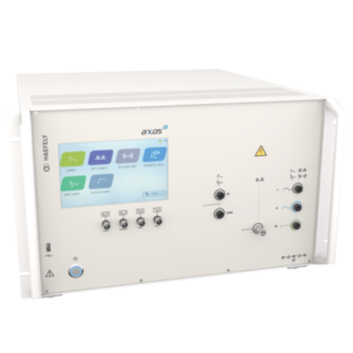
- Multi Tester with 16AMP CDN
- EFT/Burst 5kV IEC 61000-4-4
- Surge, Combination Wave 7kV IEC 61000-4-5
- Surge Magnetic field IEC 61000-4-9 (MSURGE-A loop antenna required)
- Ring Wave, 7kV IEC 61000-4-12 & ANSI
- Telicomm Wave, 7kV IEC 61000-4-5 & ITU
- AC Dips/Drops IEC 61000-4-11 (DIP 116 dips transformer required)
- DC Dips/Drops IEC 61000-4-29 (2x DC supplies required)
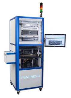
RAPIDO is a multi-site programmer for inline programming and testing.
Are you developing your next electronic assembly and are dealing with "test and programming" concerns?
Your complex boards feature difficult to contact fine-pitch components (e.g. BGA, FPGA) while test and programming still must be efficient?
RAPIDO is an outstanding, "lightning-fast" solution for programming and test using embedded system access (ESA) technologies. Special mechanics ensure precise board contacting from both sides, even for high probe counts.
The system can easily be integrated into a production line, keeping up even with high-volume manufacturing cycle times.
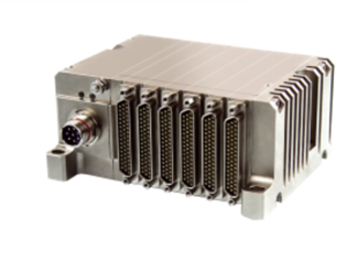
- Designed for Harsh Environments: – 50°C / +105°C, Waterproof, Shocks, Vibration, Lightning, EMI/EMC
- Ultra Compact: Generic analog module, 2×3’’ / 51×76 mm, from 1 to 16 modules per stack
- Best Data Ever: 500 ppm in extreme temperature range
- Easy to Configure: eZ software Suite, XML schema (MDL)
- INET Ready: UDP communication, IEEEE1588 synchronization, SNMP
- Multi Format Output Stream: PCM Chapter 4, Chapter 7, Chapter 10, UDP, IENA, DAR
- MIL-STD-1275E Compliant: Dedicated design for conducted susceptibility testing on 28VDC circuits.
- Spike & Surge Testing: Handles spikes up to 260V / 2J and surges up to 200V / 470J.
- High Current Capability: 16A continuous or up to 400A with the optional DM400 decoupling diode module.
- Adjustable Waveforms: Configurable rise times, pulse durations, and voltages for precise test conditions.
- User-Friendly Control: Remote interface via RS232 or USB, with optional control software for automated testing.
Enhance your EMC testing with the PG1275E Pulse Generator—precision, compliance, and versatility combined.
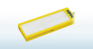
The Broadband sleeve antenna was developed to efficiently perform proximity radiation immunity testing.
The international standards ISO11451-3/ISO11452-9 stipulate proximity radiation immunity testing methods that assume electromagnetic interference when wireless transmitters such as smartphones and Wi-Fi devices are placed in close proximity to other electronic devices.
This product is a small, lightweight, high-gain antenna used in these standards that covers a wide bandwidth and has good radiation characteristics. Since it can be used in the wide band from 5GHz to 8GHz, it can be used to perform proximity radiation immunity testing assuming wireless LAN in the 6GHz band (up to 7.125GHz).
NoiseKen
For over 40 years from its foundation in 1975, Noise Laboratory has been focusing on immunity test equipment and related solutions.
Now their product lines include various types of immunity test equipment ranging from those conforming to IEC 61000-4 series standards, other international or national immunity standards and even to customer's in-house test standards.
Contact Details
Shinyei Corporation of America Head Office - Sole Authorized distributor of NoiseKen products