You design the future. We help you make it happen.
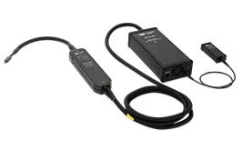
Teledyne LeCroy - AP033 500 MHz Active Differential Probe
Fully Integrated: With the ProBus™ interface, the AP033 becomes an integral part of the oscilloscope. The probe sensitivity and offset can be controlled from the oscilloscope front panel, the probe front panel, or by using remote control commands (GPIB or RS-232). Sensitivity, offset, input capacitance, and common mode voltage range are displayed on the oscilloscope screen. When used with a LeCroy digital oscilloscope, no external power supply is required.
Wide Dynamic Range: The AP033 provides a range of sensitivities from x10 gain to ÷10 attenuation (even ÷100 with plug-on attenuator) for diverse signals. The sensitivity can be adjusted continuously from 200 µV/div to 1 V/div, when used with a LeCroy oscilloscope.
At high sensitivities, the x10 GAIN and the ÷1 ATTENUATION are selected. This produces 4 nV/√Hz input noise, ±5 V of common mode voltage range (CMVR), and ±400 mV of DC differential offset. At lower sensitivities, the x1 GAIN and ÷10 ATTENUATION are selected, resulting in ±50 V CMVR and ±4 V of differential offset.
The input capacitance is just 2 pF/side (1 pF differential) whenever the ÷10 ATTENUATION is selected. Deflection factors of 2 mV/div to 1 V/div can be obtained with only 2 pF/side input capacitance and ±50 V CMVR.
DC CMRR is greater than 10,000:1 (80 dB) in both ATTENUATION settings.
OFFSET up/down buttons allow OFFSET control from the probe amplifier body. Momentarily holding both buttons will zero the OFFSET.
A supplied AC coupling capacitor head (0.1 µF) allows operation with large common mode or differential DC inputs.
The input attenuator automatically changes from ÷1 to ÷10 when too much common mode signal is sensed. This and a fast input protection circuit also serve to protect the input from potentially damaging signals. When the probe is removed from the oscilloscope or the power is turned off, the ÷10 ATTENUATION is automatically invoked, leaving the inputs protected when not in use.
Gain and Attenuation
Selections The AP033 consists of a probe head with ÷1 or ÷10 attenuation and an amplifier body which attaches to the scope front panel. The amplifier gain can be either x1 and x10. Both the probe head attenuator and amplifier gain are controlled through the ProBus interface. Normally the GAIN and ATTENUATION selections are accomplished by the oscilloscope as shown in the table below.
There are two ways of obtaining x1 gain from the AP033: x1 GAIN with ÷1 ATTENUATION, or x10 GAIN with ÷10 ATTENUATION. The oscilloscope selects the latter of these two options (as shown below) to provide minimum input capacitance and maximum common-mode dynamic range while still leaving low noise operation available at the highest sensitivity.
By using the probe amplifier body control to override the automatic selection, the x1 GAIN with ÷1 ATTENUATION option is readily available for 10 mV, 20 mV and 50 mV/div. CMVR is ±5 V, input capacitance is 5 pF, and noise is 9 nV/√Hz. Similarly, x10 GAIN and ÷10 ATTENUATION can be selected at 2 mV/div and 5 mV/div for 2 pF input C and ±50 V CMVR. The oscilloscope displays the correct deflection factor in all cases.
Using the supplied accessory plug-on attenuator head, gain selections from 100 mV/div to 10 V/div are available.
Input Characteristics
The input capacitance is modeled by 2 pF to ground from each input plus 0.20 pF from input to input when the ÷10 ATTENUATION is selected. This is equivalent to 1.20 pF differential input capacitance. With ÷1 ATTENUATION, the differential input capacitance is 2.7 pF.
Input resistance is 1 Mohm at all GAIN and ATTENUATOR settings, including the accessory plug-on attenuator head.
An AC coupling plug-on accessory features a 0.1 µF coupling capacitor for each input. The low-frequency CMRR is reduced.
Autobalance
Holding both offset buttons down for two seconds with the input connections removed invokes Autobalance. This provides the highest accuracy on all ranges by removing residual DC offset from the probe.
Low Noise
At full gain, the noise is less than 4 nV/√Hz, the lowest of any available differential probe.
Common Mode Sensing and Input Protection
It is not uncommon for a differential amplifier to be connected to a signal whose common- mode voltage exceeds the amplifier''s common-mode range. Faulty readings, including total loss of signal, can result. The AP033 senses when signals exceed ±5.5 V and switches its input attenuator into the signal path. The oscilloscope shows the new deflection factor, and the probe continues to work.
The same mechanism protects the probe from damage due to large input signals. The probe amplifier is protected from large, fast-rising signals until the input attenuator can provide permanent protection. This takes about 1 ms. With the input attenuator in place, the input can withstand 200 V DC indefinitely.
More Product Information

- 100 MHz, 200 MHz, 350 MHz, 500 MHz and 1 GHz bandwidths
- Up to 4 GS/s sample rate
- Long Memory – up to 20 Mpts
- 10.1” capacitive touch screen display
- 16 Digital Channel MSO option
- MAUI - Most Advanced User Interface
- Designed for Touch
- Built for Simplicity
- Made to Solve
- Advanced Anomaly Detection
- Fast Waveform Update
- History Mode - Waveform Playback
- WaveScan - Search and Find
- Multi-Instrument Capabilities
- Protocol Analysis - Serial Trigger and Decode
- Waveform Generation - Built-in Function Generator
- Digital Voltmeter and Frequency Counter
- Future Proof
- Upgradeable Bandwidth
- Field Upgradable Software and Hardware Options

- 500 MHz - 4 GHz bandwidths
- Up to 40 GS/s sample rate
- 15.4” capacitive touch screen
- MAUI with OneTouch
- Powerful, Deep Toolbox
- Exceptional Serial Data Tools
- 16 digital channels with 1.25 GS/s
- Huge Applied Offset Range
- Optional Application Packages
- Ideal for GaN and SiC devices
- Highest system accuracy
- Fastest rise time
- High CMRR - 160 dB

The DigRF 3G and v4 decode are the ideal tools for powerful system level protocol debug as well as problem solving for signal quality issues. The DigRF decodes add a unique set of tools to your oscilloscope, simplifying how you design and debug MIPI digital RF systems.

- All Digital IF technology
- 10.1” WVGA (1024 x 600) Display
- Frequency range from 9 KHz up to 3.2 GHz
- -161 dBm/Hz Displayed Average Noise Level (Typ)
- -98 dBc/Hz @ 10 khz Offset Phase Noise (Typ)
- Total Amplitude Accuracy < 0.7 dB
- 1 Hz Minimum Resolution Bandwidth (RBW)
- Comes with Preamplifier
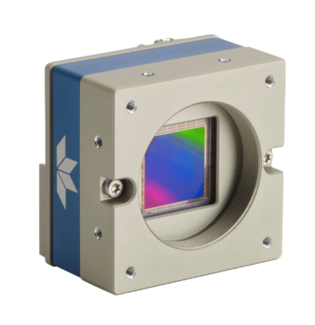
- Uses standard PC Ethernet port & hardware
- Supports cable lengths up to 100 m (CAT-5e or CAT-6)
- Simplified set-up with field proven Sapera LT software featuring CamExpert
- Engineered to accommodate industrial environment with a ruggedized screw mount RJ-45 connector
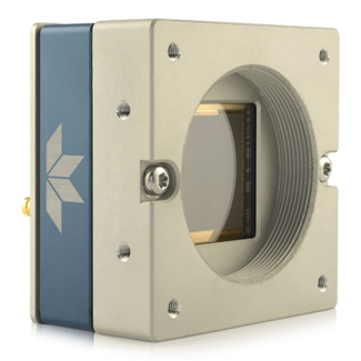
- Latest Global and Rolling Shutters sensors from Sony® - from 2 to 12 MP
- USB3 Vision interface
- Compact fully-enclosed design with features needed by modern vision systems
- Provide advanced vision performance while using less power, less space, and fitting increasingly tight industry budgets

- 2000 Vrms input
- 6000 Vpeak transients
- Up to 500 MHz bandwidth
- Ideal for Surge/EFT testing
High voltage single-ended passive probes are suitable for a wide range of applications where ground-referenced high-voltage measurements must be made safely and accurately. There is also a sense pin to automatically configure the oscilloscope for use with the probe.
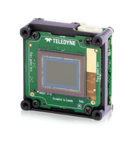
- 10 GigE Ethernet port & hardware
- Industry’s smallest 67M 10GigE Vision camera
- Simplified set-up with field proven Sapera LT software featuring CamExpert
- Engineered to accommodate industrial environment with a ruggedized screw mount RJ-45 connector
Teledyne LeCroy
Website
12bit MSO's 40 Mhz to 100 GHz, Probes, Series Network & Logic Analyzers
