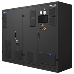
Sorensen - i-BEAM Series - High Performance, Bidirectional, Regenerative Programmable DC Power System
- Single system power up to 650 kW Parallel system power up to 1.3 MW
- Output voltage up to 1,000 V
- Bidirectional output current up to ±1,000 A, up to ±2,000A in parallel
- Available in 1, 2 or 4 channel configurations
- Multiple channel units share internal DC Bus up to 2MW without drawing additional power from the AC Grid
- Regenerative to 96%
- Large 15-inch color touch panel
- Short circuit proof
- Designed for safety to EN ISO 13849-1
- Dedicated Battery Testing/Simulation Modes
- Seamless transition between source and sink
- High reliability, long life components
The Sorensen™ Intelligent-Bidirectional Energy AMplified (i-BEAM) Series is the newest addition to the AMETEK Programmable Power portfolio of high-power testing solutions. The new i-BEAM series features full DC source and sink capabilities with power levels from 60 kW up to 1.3 MW. The i-BEAM series is fully scalable up to 650 kW and beyond up to 1.3 MW with parallel systems. The available voltage ranges of 80V, 300V, 600V, 800V and 1,000VDC provide full power up to 1,000A within a single system. Single-channel, 2-channel and 4-channel configurations are available.
Control via Front Panel Touchscreen and Digital or Analog Control Interfaces
The i-BEAM Series can be operated from the intuitive, front panel touchscreen that enables the user to easily setup, control and monitor the Output Programming Parameters, Supervisory and Set Point limits, Measurements, and System Settings. Additionally, a variety of communication control interfaces are available including; VNC Ethernet, Modbus, CAN Bus, EtherCAT, Profibus DP, Profinet, LabVIEW, Matlab/Simulink or high-speed Analog control.
Applications
The i-BEAM Series is designed for testing today’s complex, high power electronics for the aerospace, industrial, automotive and energy storage markets in a variety of applications. This platform covers all test needs through the product life cycle from advance research and development (R&D), to design validation, and production test requirements.
The i-BEAM Series offers a variety of single-channel, two-channel and four-channel models rated at 35kW to 650kW. Output voltage ratings include 80V, 120V, 300V,600V, 800V and 1000V, with current ratings of 200A, 600A and 1000A. Refer to order information at the end of this data sheet for exact model numbers
|
AC Input Specifications |
|
|---|---|
|
AC Input Voltage and Frequency |
380/400*/440/480/500/690 V ±10%, 3-phase, 50/60 Hz ±6% |
|
Power Consumption |
113 kVA |
|
Maximum Power Loss |
12.2 kW |
|
Power Factor (at rated power) |
> 0.99 ind. |
|
Total efficiency at Full Load |
Voltage: 94.8 % Current: 89.1% |
|
Current (maximum per phase) |
181 A at 400 V -10% |
|
Rated Conditional Short Circuit Current |
50 kA |
|
Recommended Pre-Fuse |
3 each Class gL/gG 200A |
|
Recommended Cable Cross Section |
1 x 95 mm2 per terminal, ≥ 50 mm2 PE |
|
Recommended Cable Lug |
M10 |
|
Rectifier Implementation |
Isolation Transformer (DC terminal is floating) |
|
DC Output Specifications |
|
|---|---|
|
Power |
35 kW to 650 kW |
|
Voltage |
5 – 1,000 VDC |
|
Voltage Ripple |
≤ 0.1% Effective Full Scale |
|
Current |
± 1,000 A |
|
Current Rise Time |
< 1 ms (300V – 800V) < 1.3 ms (1,000V) |
|
Current Ripple |
≤ 0.1% Effective Full Scale |
|
Internal Resistance (Single Operation)1 |
-10 mΩ to +1,000 mΩ |
|
Internal Resistance (Parallel Operation)1 |
-10 mΩ to +100 mΩ |
|
Accuracy |
Voltage/Current: 0.1% Full Scale Power: 0.2% Full Scale of maximum DC power |
|
Tolerance (Static at Setpoint Value) |
Voltage/Current: ± 0.1% Full Scale |
|
Tolerance (Dynamic, 0-100% Inom in 3 ms) |
Simulation mode < 1%, Test mode < 3% |
|
Measurement Accuracy / Resolution) |
Voltage/Current: 0.1% Full Scale / 16-bit Resolution |
|
Short Circuit Performance |
Short circuit proof (ICW < 3 kA, short circuit not for longer time) At 200A/600A: Standard 3 kA (optional 8 kA) At 1000A: Always 8 kA |
|
Overvoltage Category |
II per EN 60664-1 |
|
Remote Sense Compensation |
5% maximum of rated output voltage |
Notes: 1. Internal resistance can be reset via interface every 100 ms. New setpoints are calculated every 1 ms and smoothed with a low-pass filter for 10 ms
|
Environmental Specifications |
|
|---|---|
|
Protection |
IP 20 per EN 60529 |
|
Protection Class |
1 per EN 61140 |
|
Operating and Storage Temperature |
+5°C to +40°C (+41°F to +104°F); EN 60721-3-3 |
|
Transportation Temperature |
-45°C to +70°C (-49°F to +158°F); EN 60721-3-2 |
|
Operating Humidity |
5% - 85% relative humidity without condensation |
|
Operating Altitude |
1,000 m (3,280 ft.) with minimum 870 hPa air pressure |
|
Acoustic Noise2 |
< 77 dB(a) |
|
Installation Site Recommendations |
Operating area with restricted access and installation on a level, Non-Flammable Floor |
|
Cable Entry |
From Below |
|
Connection Points |
Bottom Front, accessible after doors are open |
Notes: 2. The acoustic noise level of the system depends on the load, the loading duration and the environmental conditions; Measurements takes place from front in 1 m high and 1 m distance.
|
Regulatory Agency Compliance |
|
|---|---|
|
EMC Directive |
2014/30/EU |
|
EMC Standards |
EN 61000-2-4 Class 3, EN 61000-6-2, EN 6100-6-4, EN 55011, EN 61800-3 Cat. C2 (A1) |
|
RoHS Directive |
2011/65/EU |
|
General and Safety Standards |
EN 60146-1-1, EN 60146-2, EN 62040-1, EN 61439-1, EN 61439-2, EN 62477-1, EN 63000, EN 60529, EN 60721-X, EN 61140 |
|
Machine Safety Standards |
EN 60204-1, EN 61800-5-2, EN ISO 13849-1, EN ISO 13849-2 |
|
Unit Protection |
|
|---|---|
|
Output Overvoltage Protection (OVP) |
Overvoltage Hardware (HW) Protection. Programmable within voltage range, reaction time less than 1 ms Overvoltage Software (SW) Protection. Software triggered shutdown with a programmable time delay. Limit can be set closer to the maximum voltage level but should be less than the Overvoltage HW set point. |
|
Output Current Limit Protection |
Overcurrent (source) and Undercurrent (sink) are programmable within the current range. |
|
Reverse Polarity Protection |
Reverse polarity protection active when the DC Converter is off and detected by the sense lines. |
|
AC Input Protection |
Automatic shutdown if AC Inputs fall out of nameplate specifications for voltage, frequency or phase loss. |
|
Overtemperature Protection |
Automatic Overtemperature Protection shutdown when internal component temperature exceeds +40°C (+104°F). |
|
Cabinet Dimensions and Weights |
||||
|---|---|---|---|---|
|
Typical cabinet dimensions and weights. Actual dimensions and weights vary by system configuration and options. All cabinets require a minimum of 300 mm (11.8 inch) clearance to the ceiling. i-BEAM configurations of 320kW and higher require additional cabinets. |
||||
|
Cabinet No. |
Width |
Depth |
Height |
Weight |
|
1 |
1,000 mm (39.4 Inch) |
800 mm (31.5 inch) |
2,000 (78.8 inch) |
1,000 kg (2,205 lbs.) |
|
2 |
1,200 mm (47.3 inch) |
800 mm (31.5 inch) |
2,000 (78.8 inch) |
900 kg (1,984 lbs.) |
|
3 |
1,200 mm (47.3 inch) |
800 mm (31.5 inch) |
2,000 (78.8 inch) |
900 kg (1,984 lbs.) |
More Product Information

AMETEK Programmable Power
Programmable Precision AC & DC Sources, Loads and Custom Power Solutions
