You design the future. We help you make it happen.
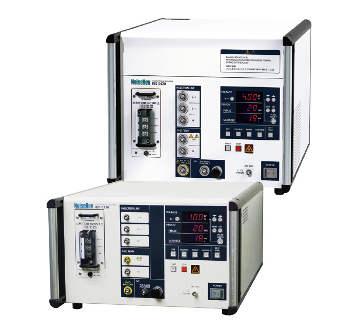
NoiseKen - Impulse Noise Simulator (INS series)
NoiseKen simulators to reproduce fast rise-up noises which are generated when switching ON / OFF electric current on the inductive load.
Since the pulse includes broadband frequency and its rise-up time is fast at 3ns or less, it can make the noise coupling dense and effective to reproduce the malfunctions of electronics equipment under the test.
It can realize performance evaluation of electronics equipment's upon reproduction of line noises which are intruded to the power supply lines or induced noises onto the telecommunication lines.
Discontinuation notice of INS-4020 / 4040 and INS-AX2 series:
In observance of the Minamata convention on mercury, products that include mercury have been restricted of export from Japan. This includes the INS-4020, INS-4040, INS-AX2 series that used a mercury relay switch, and now have been succeeded by the INS-S220 and INS-S420. Maximum output voltage of INS-S220 is 2kV, and that of INS-S420 is 4kV.
Specification
|
Parameter |
INS-220 |
INS-S420 |
|
|---|---|---|---|
|
Pulse Setting-1 |
0.50kV ~ 0.99kV ±10% 0.01kV step |
- |
|
|
100ns ~1000ns ±10% 50ns step |
|||
|
1ms ~ 999 ms ±10% 1ms step |
|||
|
Pulse Setting-2 |
1.00kV ~ 2.00 kV ±10% 0.01kV step |
0.50kV ~ 4.00kV ±10% 0.01kV step |
|
|
50ns ~ 1000 ns ±10% 50ns step |
50ns ±15%、100ns~1000ns ±10% 50ns stepp |
||
|
10ms ~ 999 ms ±10% 1ms stepp |
|||
|
Output Voltage |
0.5 ~ 2.00kV±10% (10V step) |
0.5 ~ 4.00kV±10% (10V step) |
|
|
Polarity |
+ / - |
||
|
Rise Time |
<3ns |
||
|
Output Impedance |
50Ω |
||
|
Terminal Resistor |
50Ω |
||
|
Pulse Repetition Mode |
LINE PHASE |
50Hz/60Hz coupling phase angle 0 ~ 360°±10° synchronized with L-N of EUT supply or external CDN |
|
|
VARIABLE |
1ms ~ 999ms ±10 %(~ 1kV)10ms ~ 999ms ±10 %(1kV ~ 2kV |
10ms ~ 999ms ±10 % |
|
|
EXT TRIG |
Period:>10ms Input signal level:TTL/open collector negative logic Pulse width:>1ms Also functions for timing reference signals input from an external injection unit. |
||
|
1 SHOT |
Single pulse generation, each time the 1 SHOT button is pressed. Synchronized (phase angle set on the PHASE control) or asynchronized pulse period. |
||
|
Memory Storage |
5 tests |
||
|
Test Time |
1s ~ 999s ±10% 1s step |
||
|
Coupling Switch |
L(+), N(-), PE / PULSE OUT ※manual switch by coaxial cable |
||
|
Coupling Mode |
common-mode / normal-mode ※manual switch by short plug |
||
|
EUT Power Capacity |
Single phase AC240V / DC125V 16A (L(+), N(-), PE) |
||
|
External Control |
- |
RS-232C compliant optical communication |
|
|
Power Supply |
AC100 ~ 240V 50Hz/60Hz |
||
|
Operating Temperature / Operating Temperature |
15 ~ 35℃ / 25 ~ 75% |
||
|
Dimensions / Weight |
(W)430×(H)249×(D)540mm (protrusions excluded) / approximate 20kg |
(W)430×(H)349×(D)540mm (protrusions excluded) / approximate 23kg |
|
|
HV Coaxial Cable |
NMHV type ※ NoiseKen original |
||
|
Accessories |
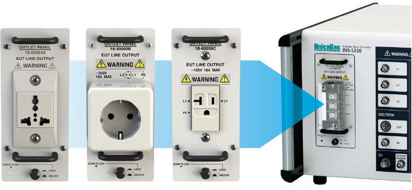
coaxial cable 30cm (02-00013A): 2pcs, SG short plug (02-00106A): 1pc, SG cable (05-00103A): 1pc, outlet panel: 1pc, AC cable: 1pc, manual instruction: 1 volume, accessory bag: 1pc |
||
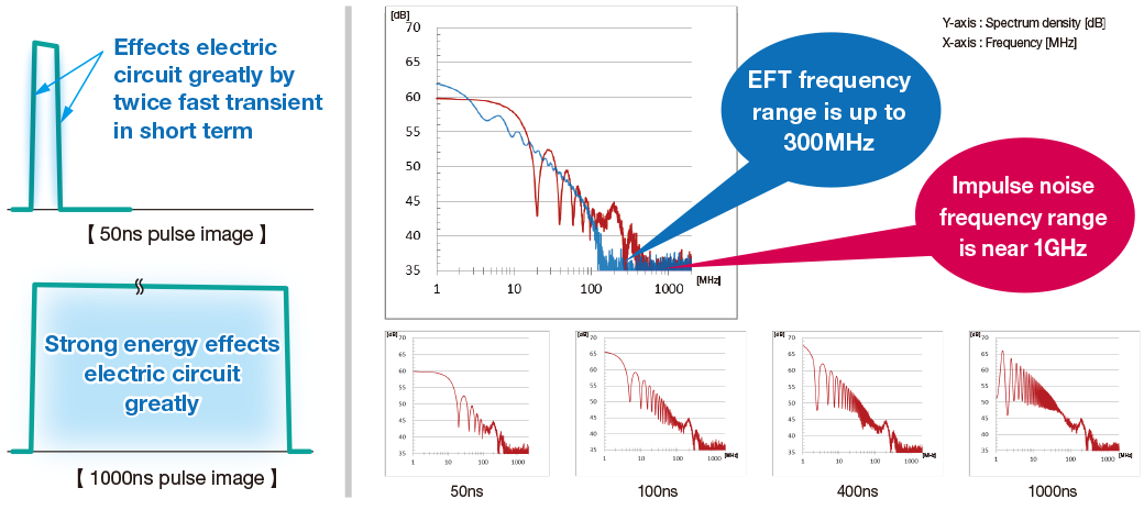
To solve the trouble in the market high frequency, energy volume of test pulse can be adjustable
Even narrow pulse with 50ns-100ns width contains less energy, twice fast transient due to rise and fall and inducted coupling occurred by sharp electromagnetic field effect electric circuit greatly.
Wide pulse with 800ns-1000ns contains more energy, so voltage fluctuation is easily to effect circuit.
The rise time of impulse simulator is faster than IEC61000-4-4 fast transient/burst test, so spectrum is high. When it injects noise to EUT, noise is easier to invade electric circuit internally.
Spectrum and amplitude is different due to Impulse width, so it is recommended to test with different pulse width.
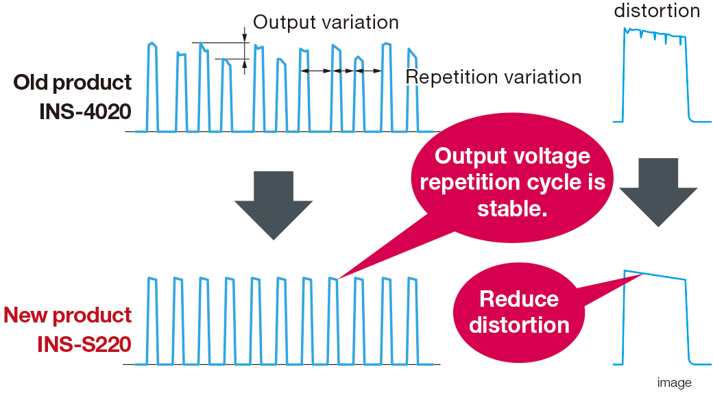
Test reproduction is improved. More quantitative test is available.
The usual mercury relay changes into semiconductor relay, so test pulse stability is improved. More quantitative and high reproduction test is available. Also, waveform distortion due to mercury relay's deterioration.
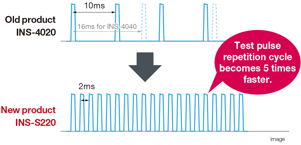
Mal-function rate is up. Test time is to be shortened.
The repetition of pulse in test is faster than the old product. Mal-function rate is up and test time is expected to be shortened.
Connection is simplified. Connection time is shortened.
Outlet panel to which EUT is easyily to be connected is adopted. EUT is easy to connect by using outlet panel ( sold separately ) complying to each country's socket shape.
INS Test Setup Example
Method or test to power supply lines
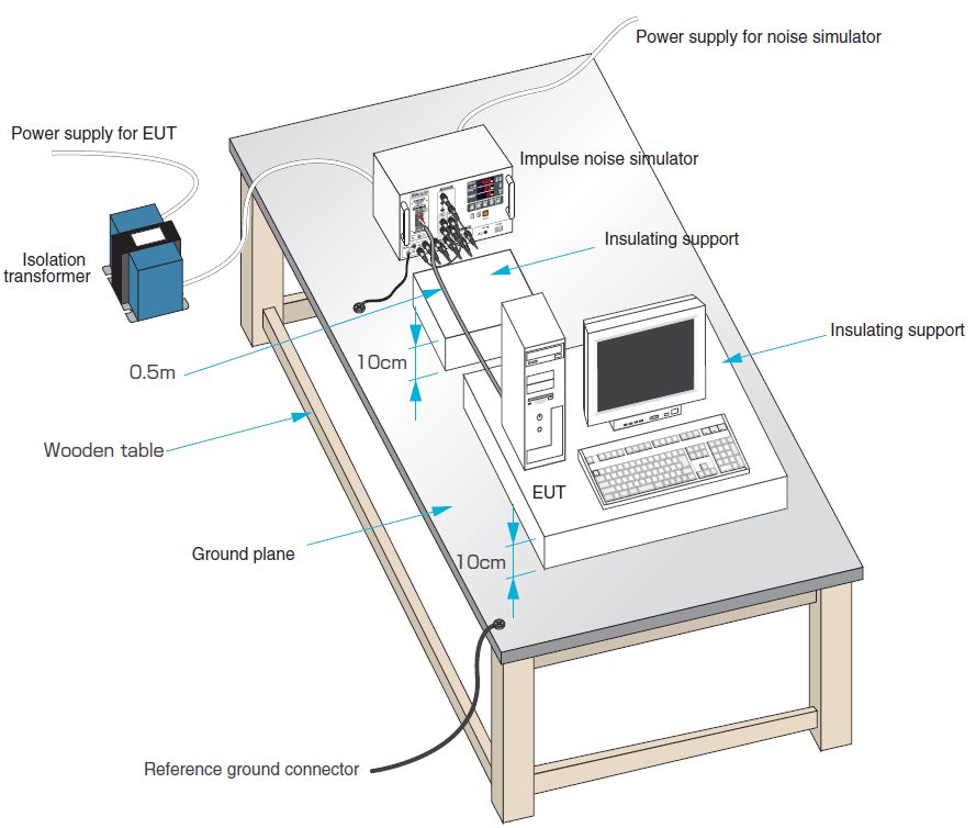
- Connect power supply line for EUT to EUT LINE INPUT on the simulator main unit (hereafter called as main unit) through an isolation transformer
- Lay a ground plane and insulation sheet under main unit and EUT, and ground them for securing
- Connect power supply cable of EUT to main unit (Fold and bind the cable so it can be short in case the length is long)
- Connect short adaptor to SG. Connect SG terminal of main unit and FG terminal (In case it is there) of EUT to ground plane with low impedance braided wire shortly and securely
- Connect 50Ω TERM OUT connector to connector of phase (L1 or L2, PE if necessary) the noise is intended to be injected with coaxial cable
Method or test to interconnection lines
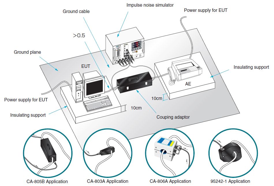
- ①Lay a ground plane and insulation sheet under main unit and EUT, and ground them for securing
- Open coupling adaptor CA-805B (Option) and clamp interface cable with the adaptor. Connect connector of the adaptor to PULSE OUT of main unit. Connect the one another connector of the adaptor to 50Ω TERM IN of main unit. In case for coupling adaptor CA-803A (Option), connect PULSE OUT of main unit and connector of the adaptor
- Connect power supply cable of EUT to arbitrary power source since no high voltage pulse is injected in this test
- Connect SG terminal and FG terminal of EUT to ground plane
More Product Information
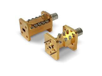
- High-level noise modules mounted on a circuit board
- Modified BW, output power, and flatness specifications
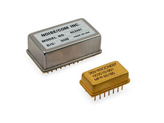
The NC2000 Series amplified noise modules are an excellent choice for high-level noise modules mounted on a circuit board. The NC2000 Series modules are housed in 24, or14-pin dual-inline packages. The NC4000 series modules are housed in a 40-pin module that cover similar noise bands to the NC2000, but have higher crest factor, and 60 dB of TTL controlled attenuation. Modified BW, output power, and flatness specifications are available for these modules. Please consult Noisecom for availability, and appropriate package style.

Measurement Accuracy
- Best solution for high accuracy IV/CV, low-noise and 1/f measurements with PureLine, AutoGuard and next generation MicroChamber technologies
- Minimize AC and spectral noise with effective shielding capability
- Achieve unsurpassed RF/mmW measurement and calibration accuracy with integrated RF tools and WinCal
- Shortest signal path test integration for accurate, thermally stable, and low-error data collection
See "Specifications & Details" tab for more key features
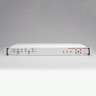
- Network Enabled Distribution Amplifier
- Low Phase Noise Reference Frequency Outputs
- Fault Alarm Output
- 1U 19″ Rack Mount
- Frequency Synthesizer Option
- Hitless Switching of Reference
- Programmable Amplitude
- Propagation Delay Compensation
- 10 MHz Standard, Other Frequencies Available
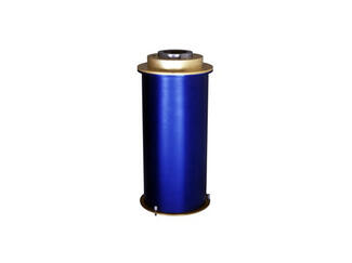
- Outstanding stability
- Fast switching speed
- Ripple-free response over standard waveguide bands
The NC5000A Series AWGN noise sources feature outstanding stability, switching speed, and ripple-free response over standard waveguide bands. The high stability of the NC5000A Series allows these units to be used in place of cumbersome gas tube noise sources.
Ripple in the output of noise sources has a direct effect on measurement accuracy, so Noisecom has tailored the response of the NC5000A Series so that ripple is minimized throughout the specified frequency range.

Simulator to reproduce various transient surge phenomena which are generated in a vehicle and required in the international standard ISO-7637-2 (2004) Standard, and evaluate the immune resistibility of the equipped electronics devices against the surge.
- ISO 7637-2 (2004) Standard compliant simulator
- Correspondent to the test for 12V/24V/42V systems in a vehicle
- Stand-alone usage per the each generator unit possible as well as the comprehensive control
- Large capacity CDN (60V/50A) available (Option)
- Up to 200A power supply possible (Option)
- Windows in Japanese applicable for the software program as well
Private standards or specifications by manufactures can be responded upon request.
- Expandable frequency range from 18 to 325 GHz
- 2 to 3 times better accuracy
- Automatic Nitrogen purge eliminates helium equipment
- Primary calibration standard
- Radiometer reference source
- SATCOM earth station conformance verifications
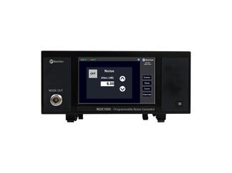
- 5” touch screen display
- Noise output through female N connector
- Ethernet connection for remote control
The NGX1000 programmable noise generator is a high performance, broadband additive white gaussian noise (AWGN) generator in an easy-to-use compact form factor. The streamlined user interface and flat menu structure provides a fast, simple way to add RF noise in a communications system to test reliability, robustness and performance.
All functionality of the generator is accessible through the 5” touch screen or via remote control through an ethernet connection delivering flexible, programmable noise generation for broad use in semiconductor, military, aerospace, satellite, medical and communications applications.
- Automated Absolute and Additive (Residual) Measurements
- Real Time Cross Correlation
- Only analyzer available that allows actual noise floor measurement
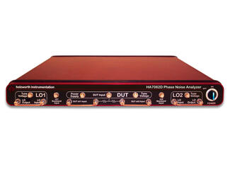
- Unparalleled analog performance
- Repeatable data
The HA7162D Real Time Phase Noise Analyzer delivers proven accuracy, high reliability, automation and flexibility. The real time engine covers the full measurement bandwidth with extremely fast measurement speeds to reduce product development time and optimizes ATE manufacturing throughput.
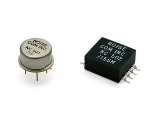
- Complete bias circuits
- Requires no external components
- Extremely flat output power versus frequency characteristics
The NC500 (through-hole) and NC500SM (surface mount) Series noise modules are an economical solution for built-in test requirements. They contain complete bias circuits and require no external components. Some models contain additional gain stages for high power ENR output (51 dB). The surface mount package is suitable for mounting on micro strip. The modules have extremely flat output power versus frequency characteristics that are insensitive to temperature and voltage variations.
NoiseKen
For over 40 years from its foundation in 1975, Noise Laboratory has been focusing on immunity test equipment and related solutions.
Now their product lines include various types of immunity test equipment ranging from those conforming to IEC 61000-4 series standards, other international or national immunity standards and even to customer's in-house test standards.
Contact Details
Shinyei Corporation of America Head Office - Sole Authorized distributor of NoiseKen products
")