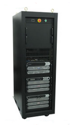
Sorensen - DC Power/Energy Absorber Test System (Sponge)
- Energy absorber with a rating of 400VDC at ±150A
- Provides up to 400V at 150A for 60kW of output power
- Energy Absorber Load chassis creates a total resistance of approximately 1.5 Ohms at 30kW continuous and 60kW peak
The Energy Absorber Test System includes power supplies and a regenerative energy absorber with a rating of 400VDC at ±150A. The system consists of DC power supplies, an AC distribution and interlock system, an energy absorber chassis and an absorber load resistor chassis. The power sources are equipped with a remote control option allowing control via GPIB or with front panel controls in local mode. The operation of the specific parts of the system is described in the sections below.
DC Power Supplies
The power supplies consist of two model types each rated for 0-400VDC at 75A. The SGI supply includes a GPIB programming interface and operates as the Master supply. The SGA supply is used as a Slave, operating as a voltage controlled current source. This Master/Slave operation is used to provide up to 400V at 150A for 60kW of output power. By operating in a Master/Slave configuration, the supplies operate as one unit that can be controlled from the Master unit through either local control or IEEE-488 operation. The DC power supplies contain a provision for voltage and current readback. The current readback on the front panel of the supplies is set up so that the SGI supply indicates the sum of both supplies. As used in this system, the power supply current monitoring indicates the actual power supplies output current. Regenerative current is not conducted through the power supplies due to a blocking diode in the Energy Absorber chassis so the system current readback is available separately.
Energy Absorber Load Chassis
The Energy Absorber Load chassis contains the regenerative resistive load element. The load consists of numerous high power resistors connected in series/parallel banks, creating a total resistance of approximately 1.5 Ohms at 30kW continuous and 60kW peak.
Energy Absorber Control Chassis
The Energy Absorber Control chassis contains primary and secondary voltage clamps consisting of an IGBT and an SCR. In addition, it contains a GPIB programmer and measurement circuitry and controls that provide drive signals to the power components. In the chassis, high current bus capacitors are connected between the output to limit the rate of rise of voltage (slew rate) allowing the IGBT to operate at a controlled frequency when an external Regen current pulse occurs and to store energy to provide high peak current pulses to the load. A blocking diode in series with the input power supplies is used to detect the direction and amplitude of current flow. A differential amplifier is used to monitor the voltage across the blocking diode and regulate it to a value programmed by the internal GPIB controller which is independent of the input voltage level. Since it is desirable in some tests to allow the voltage to increase above the normal voltage level during the Regen pulse event, the output occurring across the blocking diode is scaled so that the voltage that is fed to a comparator is proportional to the controllers D-A converter that is calibrated to this same voltage range. When currents from the actuator conduct back into the absorber chassis, the bus capacitor charges until the input to the comparator reaches the programmed threshold and activates a drive signal to turn on the power IGBT connecting the absorber load resistor across the output bus. The resistor discharges the output capacitor until a lower threshold voltage is reached on the comparator. In this manner, with the actuator Regen current providing the charging current and the absorber load resistor providing the discharge current, the bus capacitor bank voltage can be maintained at a constant level with approximately 5V peak to peak of ripple during the charge and discharge intervals. The Energy Absorber Control chassis also contains circuitry to activate AC input contactors, relays and power supply shutdown signals, which are enabled through a control connector. Also available are high bandwidth 0-10V analog circuitry proportional to the DC output voltage and current for monitoring with an oscilloscope or external analog system. The voltage and current monitors are also available on an internal GPIB controller in the Absorber chassis so that their values can be queried over the bus. Additional functions in the chassis include an OVP detector for a secondary protection SCR in the case of a power interruption, and front panel status LEDs to show the operating status of the OVP circuit, relays and contactors. The oscilloscope photo example shows the action of the power supplies and regen circuitry to a specific loading condition. The photo shows an expanded view of the output voltage where the charge and discharge intervals are more visible. The bottom trace is output current that on the Energy Absorber power rack during a pulsed regenerative event. The top trace (1) shows the output voltage programmed to 270VDC at 10V/div AC coupled. The lower trace (3) shows the load current at 100A/div being switched between a resistive load of 100A and the Regen current at 150A. The arrow at the center of the scope trace is the zero current level. The scope trace is shown at 4msec/div.
Communication
Communication to control the power supply outputs and readback of voltage and current in the power supplies is accomplished with a GPIB interface using standard SCPI commands. The power supplies can also be operated manually from the front panels. The Energy Absorber chassis includes a GPIB interface for programming the Regen clamping limit, input contactor closure, dropout relay closure and voltage and current readbacks. A GPIB connection is provided on the rear of the rack for both interfaces.
AC Control and Distribution
The power rack system includes an AC distribution system. With a DC output power rating of 60kW at 480VDC and 150A, the AC input current to the rack is 120A per phase with a 400VAC, 3 phase, 4 wire connection. AC power to the racks is through two pin and sleeve type connectors and routed through circuit breakers and the mains disconnect interlock contactors. The AC interlock operates by energizing relays which are operated by ON/OFF switch closures located on the front panel or with auxiliary switch closures which are available through a rear I/O panel connector. The ON/OFF panel contains two pushbutton switches, an ON pushbutton and a twist to lock OFF button. A door interlock and single point ground connection are also provided.
DC Output
DC output is through an MS type connector of suitable type and ampacity on the panel depicted in the image above. A mating connector is provided.
|
Input |
|
|---|---|
|
Voltage |
480VAC ±10% L-L 3 Phase, 3 Wire plus ground |
|
Frequency |
45-65 Hz |
|
Current |
60A per phase max on two AC inlets at full rated output power |
|
Power Factor |
0.65 minimum |
|
Connections |
Hubbell 460B7W AC Inlet IP67 AC Inlets two (2) each |
|
Output |
|
|---|---|
|
Voltage |
0-400VDC |
|
Current |
0-150A |
|
Connections |
MS3102A-36-6S |
|
Efficiency |
85% typical @ full load |
|
Energy Absorber |
|
|---|---|
|
Current Rating |
150A nominal, 335A peak for 50usec |
|
Power Rating |
20KW average, 50kW peak for 1 sec |
|
Overvoltage |
OVP set at 430VDC |
|
Remote Control Interface |
|
|---|---|
|
Discrete Control |
I/O D38999/20F35PN MS Connector |
|
IEEE-488 |
Programming GPIB Connector |
|
AC Power Control |
|---|
|
Power ON pushbutton on front panel (green) |
|
Power OFF/Emergency locking pushbutton on front panel (red) |
|
AC present indicator on front panel |
|
Remote interlock pins on rear panel control connector |
|
Physical Characteristics |
|
|---|---|
|
Height |
73 inches(including casters) |
|
Width |
24 inches |
|
Depth |
36 inches |
|
Weight |
766 lbs.max |
|
Cabinet Color |
Black, FED STD 595B,27038 |
|
Dress Panel Color |
Black, FED STD 595B,27038 |
|
Other |
Locking Casters; lifting eyebolts |
|
Environment |
|
|---|---|
|
Temperature |
0-50 C Ambient |
|
Humidity |
95% max, non condensing |
|
Altitude |
4,000 ft |
|
Certifications |
|---|
|
Sorensen SGA power supplies are NRTL approved to UL102, UL61010, EN61010, IEC61010 |
More Product Information

AMETEK Programmable Power
Programmable Precision AC & DC Sources, Loads and Custom Power Solutions
