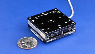
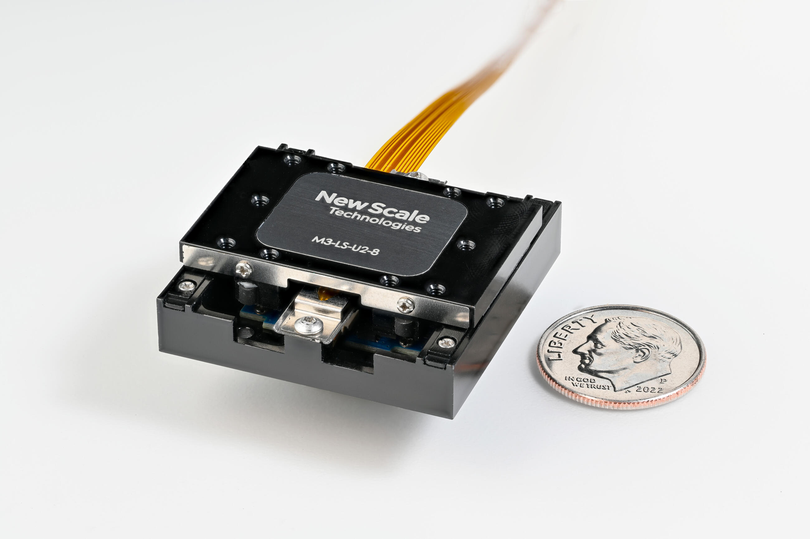
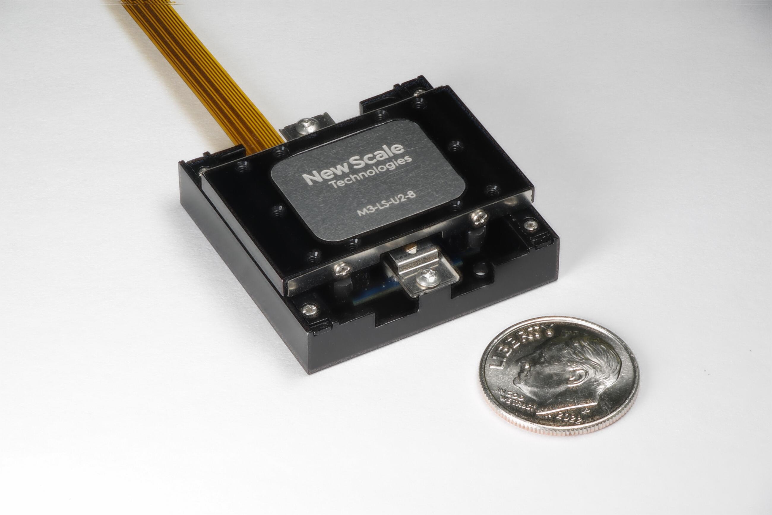
New Scale Technologies - M3-LS-U2-8 linear smart stage & developer kit
- Up to 96 differential channels per full rack mainframe
- Constantly monitor input signals for fault conditions
- Flexible configurations for detecting edges, out-of-bounds conditions and measuring pulse widths
- Inputs can be masked, inverted, and combined to produce interrupts
- Can be used as a time stamp module and as a digital I/O
- Programmable debounce circuitry prevents erroneous readings
- 10 V and 100 V input ranges
- On-board memory stores events with IEEE 1588 timestamps
- Synchronize reading of input states with other scanned analog channels
The EX1200-7416 has sixteen true differential channels of analog comparator input that can be selected to provide an interrupt to the EX1200 system when the input falls outside the software programmed bounds, independent of the scan list operation. The EX1200-7416 is an ideal device in “go/no-go” testing, where a device fails if the voltage outputs exceed a threshold or window, or in control applications where a device or test needs to be shut down if a voltage level is exceeded. Using an analog comparator/interrupter in certain applications, as opposed to a traditional scanning approach, considerably improves the overall response time of the system, providing the ability to ‘constantly monitor’ signals of interest for fault conditions.
The inputs are independently software programmable, permitting the user to vary input thresholds per channel. Each input signal is also digitally debounced for a programmed time ranging from 1 μs to 500 ms, preventing input signal noise from causing undesired interrupts. The threshold polarity can be programmed to detect either a rising or falling edge or can be masked to prevent unused channels from causing interrupts. All of the enabled inputs are OR’d together to produce a single interrupt signal. Input can be combined via math functions to create virtual channels when multiple conditions must be satisfied before an event is recorded. On board memory stores events with precise IEEE 1588 timestamps. The interrupt signal can be routed through the front panel connector for distribution to other devices in the test system for absolute deterministic communication.
There are three modes of operation that satisfy a wide range of applications. In normal mode, any channel crossing a threshold with the programmed polarity will cause an event to be latched into memory. Window mode automatically parallels two adjacent input channels and is used when an input signal is expected to be within upper and lower bounds. Pulse mode provides a means for measuring the pulse width of input signals by automatically changing the threshold polarity at each crossing.
More Product Information

New Scale Technologies (NST)
Embedded Motion Modules Make Great Products Smaller
Founded in 2002, NST develops, licenses and manufactures standard and customized embedded motion modules that fit on your fingertips. These include rotary and linear smart stages that incorporate our patented and proprietary technologies: SQUIGGLE® and UTAF piezoelectric ultrasonic motors, position sensors, precision bearings, drive and control circuits, and microprocessors with closed-loop firmware that connect to New Scale Pathway® PC software.
