You design the future. We help you make it happen.
BOLAB Systems GmnH - 4-Quadrant Voltage Amplifiers 400 - 54,000W
- DC - 200 kHz bandwidth DC
- MHz (small signal -3 dB)
- Output voltage ±75 Vpk
- Rise / fall time 100 V/µs
- USB interface standard, LAN optional
- Analog control input 0 ... ±10 V for control of voltage and current
- Monitor outputs for measured voltage and current values (not all models)
- Modularly extensible via master-slave mode
- Parallel and Series Connections for two or more units
Arbitrary 4-Quadrant Voltage Amplifiers
100-TS Series 400 W - 54,000 W, DC - 200 kHz / 1 MHz
Special Features
- DC ... 200 kHz full-range bandwidth
- DC up to 1 MHz (small signal -3 dB)
- Output voltage 35 V / 70 V / 75 V
- Rise time/fall time up to 100 V/µs
- Arbitrary function with 1 Million memory data points
- Internal resistor 0 ... 200 mW (Option)
- Analog input 0 ... ±10 V for voltage control
- Option for running as a current amplifier
- Monitor outputs for measured values of voltage and current
- WaveMaster software for graphical waveform generation
- Simulation of imported oscilloscope signals
- Modularly expandable up to 54 kW (Systems > 1 kW)
- USB interface standard
- Voltage resolution less than 0.01 V
- Linearity 0,1% DC
- DC - Offset < 1 mV
- DLL’s for C++, LabViewTM, Vector-CAPL, Python, C#, MathLab, etc.
Model 35N-TS Overview
+35 V / -16 V
|
Models |
Low voltage -16 V...+16 V |
Medium voltage -16 V...+27 V |
High voltage -16 V...+35 V |
Output Power |
Size |
|
105-35N-TS |
15 A |
15 A |
11 A |
400 W |
3 U |
|
110-35N-TS |
38 A |
38 A |
28 A |
1.000 W |
4 U |
|
120-35N-TS |
76 A |
76 A |
55 A |
2.000 W |
14 U |
|
130-35N-TS |
114 A |
114 A |
83 A |
3.000 W |
18 U |
|
140-35N-TS |
152 A |
152 A |
110 A |
4.000 W |
22 U |
|
150-35N-TS |
190 A |
190 A |
138 A |
5.000 W |
26 U |
|
160-35N-TS |
228 A |
228 A |
165 A |
6.000 W |
30 U |
|
180-35N-TS |
304 A |
304 A |
220 A |
8.000 W |
2 x 22 U |
|
200-35N-TS |
380 A |
380 A |
276 A |
10.000 W |
2 x 26 U |
|
220-35N-TS |
456 A |
456 A |
331 A |
12.000 W |
2 x 30 U |
|
250-35N-TS |
570 A |
570 A |
413 A |
15.000 W |
3 x 26 U |
|
280-35N-TS |
684 A |
684 A |
496 A |
18.000 W |
3 x 30 U |
Model 110-70N-TS Overview
+70 V / -16 V
|
Models |
Low voltage -16 V...+16 V |
Medium voltage -16 V...+27 V |
High voltage -16 V...+70 V |
Output Power |
Size |
|
105-70N-TS |
19 A |
19 A |
7 A |
500 W |
3 U |
|
110-70N-TS |
38 A |
38 A |
14 A |
1.000 W |
4 U |
|
120-70N-TS |
76 A |
76 A |
29 A |
2.000 W |
14 U |
|
130-70N-TS |
114 A |
114 A |
43 A |
3.000 W |
18 U |
|
140-70N-TS |
152 A |
152 A |
57 A |
4.000 W |
22 U |
|
150-70N-TS |
190 A |
190 A |
71 A |
5.000 W |
26 U |
|
160-70N-TS |
228 A |
228 A |
86 A |
6.000 W |
30 U |
|
180-70N-TS |
304 A |
304 A |
114 A |
8.000 W |
2 x 22 U |
|
200-70N-TS |
380 A |
380 A |
143 A |
10.000 W |
2 x 26 U |
|
220-70N-TS |
456 A |
456 A |
171 A |
12.000 W |
2 x 30 U |
|
250-70N-TS |
570 A |
570 A |
214 A |
15.000 W |
3 x 26 U |
|
280-70N-TS |
684 A |
684 A |
257 A |
18.000 W |
3 x 30 U |
Model 75N-TS Overview
+75 V / -75 V
|
Models |
Low voltage -25 V...+25 V |
Medium voltage -50 V...+50 V |
High voltage -75 V...+75 V |
Output Power |
Size |
|
105-75N-TS |
19 A |
10 A |
7 A |
500 W |
3 U |
|
110-75N-TS |
38 A |
19 A |
14 A |
1.000 W |
4 U |
|
120-75N-TS |
76 A |
38 A |
27 A |
2.000 W |
14 U |
|
130-75N-TS |
114 A |
57 A |
40 A |
3.000 W |
18 U |
|
140-75N-TS |
152 A |
76 A |
53 A |
4.000 W |
22 U |
|
150-75N-TS |
190 A |
95 A |
67 A |
5.000 W |
26 U |
|
160-75N-TS |
228 A |
114 A |
80 A |
6.000 W |
30 U |
|
180-75N-TS |
304 A |
152 A |
106 A |
8.000 W |
2 x 22 U |
|
200-75N-TS |
380 A |
190 A |
133 A |
10.000 W |
2 x 26 U |
|
220-75N-TS |
456 A |
228 A |
160 A |
12.000 W |
2 x 30 U |
|
250-75N-TS |
570 A |
285 A |
200 A |
15.000 W |
3 x 26 U |
|
280-75N-TS |
684 A |
342 A |
239 A |
18.000 W |
3 x 30 U |
Selectable Operating Voltage
Three selectable operating-voltage ranges allow adapting to applications for high voltage / low current or low voltage / high current.
Especially when controlling extremely low impedance loads, the operating voltage range can be reduced to one-third of the maximum output voltage, which greatly reduces power dissipation.
- Reduction of power dissipation
- One system for 12 V / 24 V / 48 V vehicles
General
The 100-TS series are linear precision
- quadrant power amplifiers for fast voltage and current signals - each positive and negative (bipolar).
They also work as sink-in applications to absorb power. This series is characterized by extremely high bandwidth at the highest power requirements, necessary for fast signals.
Especially these amplifiers are characterized by their signal quality.
Arbitrary Functionality
BOLAB´s arbitrary power amplifiers include a huge memory of 1 Million data points to store arbitrary waveforms in the instrument. No arbitrary waveform generator or any other controlling instrument is needed, which makes these 4-quadrant amplifiers unique in the world market.
The easy-to-use WaveMaster software, which is standard in scope of delivery, allows generating waveforms with a graphical user interface or via tabular input.
Monitor Outputs
Located on the back of the instruments, there are monitor outputs for voltage and current with the respective measured values.
Output values are 0 ... ±10 V
for 0 ... ±Vrated respectively 0 ... ±IIrated.
The current is measured with an internal shunt and accuracy of approx. 1 %.
Optionally a current sensor with 0.01 % accuracy can be integrated easily.
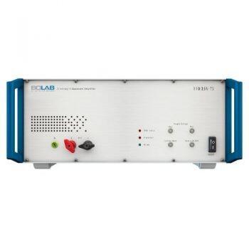
Output ON/OFF
The output on/off switch at the front of the instruments allows the output to be activated or deactivated. When deactivated, the devices under test are completely galvanically separated.
Protective Functions
Various protective functions avoid damage to the instrument and guarantee protection for the devices under test. Output voltage and current can be limited. An over-temperature shutdown is included. The unit’s internal power dissipation calculation and complete current monitoring ensure perfect short circuit and over-voltage protection. Also, for security reasons, an interlock shutdown can be triggered.
Unlimited Waveform Memory
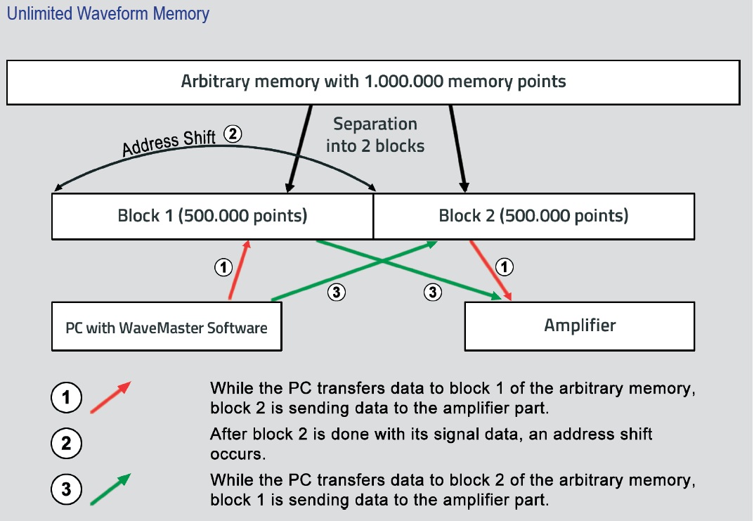
- This technology enables an endless, continuous data stream to the amplifier.
- Compared to a function generator with its limited arbitrary memory there is no limitation of the size of the waveform.
- A waveform with small spikes and interruptions of e.g. 100 µs and long constant levels in between can be simulated easily.
Voltage And Current Control
Both voltage and current control of the comprehensive amplifiers is possible. This can be selected on the front panel of the instrument.
Control input is 0 ... ±10 V
for 0 ... ±Vrated respectively 0 ... ±IIrated.
An optional compensation network for current control is necessary, which achieves the highest slew rates and signal quality for current signals.
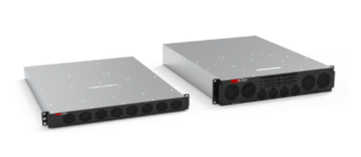
Modular Concept / Modularly Expandable
- Modular hardware architecture
- Starting with one single unit of e.g. 1 kW
- Extension up to 18 kW in parallel
- Building up 3-phase systems with up to 6 kW per phase
- Serial connection for increasing voltage
- In case of a defective module, only this module needs to be repaired
- Each module has its own indication for functional capability
WaveMaster Software
Waveform generation and 4-quadrant amplifier control
Special Features
- Easy to use graphical waveform editor and tabular input possibility
- Command library for integration into automated test systems:
- LabView(TM)
- Vector CANoe (CAPL)
- C#
- C++
- ANSI C
- Python
- etc.
- Simulation of imported oscilloscope signals
- Waveform trigger caused by external TTL signal (rising edge) for synchronization
- Macro function for the execution of automated tests
Waveform Generation
The powerful and easy-to-use WaveMaster software is unique in the world market. Without any knowledge of software development, constructing ordinary and complex waveforms is easy.
A graphical waveform editor allows the generating of individual curves in a flash. Also, tabular input can produce all kinds of waveforms immediately.
The simplicity of how fast data can be imported out of oscilloscopes is fantastic. Reading in ASCII data files is possible in the same way.
Digital Interface USB
All functionalities of the 4-quadrant amplifiers are available in WaveMaster software for controlling the instruments. Its USB interface can easily set short-time current on/off, output on/off, operating voltage range, and other functions.
Trigger Function
A hardware trigger input can be activated to monitor a TTL input signal on its rising edge. Synchronous waveform simulation, measurement, and testing tasks are predestined applications.
Macro Function
With a comfortable macro editor and its execution, selected waveforms run sequentially. Bursts, repetitions, and loops make testing easy without any software coding.
Options
- 100S.......................Sensing (0 V / 0,5 V / 1 V / 2 V) standard in systems > 1 KW
- 100I3......................3-channel isolation amplifier
- 100VR....................Variable internal resistor 0...200 mΩ
- 100CS200.............Current sensor (standard in systems > 1 KW)
- OVR HV.................Overvoltage protection for high voltage power supply in series
- 100K.......................Compensation network to run as a current amplifier
- 100MW3...............19” Adapter for 3U systems
- 100MW4...............19” Adapter for 4U systems
- FIS 60-75..............Electronic switch (60 V / 75 A)
- FIS 60-125............Electronic switch (60 V / 125 A)
- FIS 60-CS..............Cable Set for electronic switch
- FIS 60-RR..............Reference resistors (1W / 100W / 1kW)
- 700-XX..................19” rack
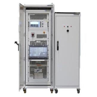
Scope Of Supply
- Amplifier system
- Power cord
- User manual
- WaveMaster software
- WaveMaster remote DLL´s
- Waveform library
- 19” rack (systems > 1 KW)
More Product Information

LUMIMAX® LED Ring Lights are ideal for the uniform illumination of flat, matte and reflective surfaces. A range of different sizes and performance classes of the LED ring light provide the optimum illumination for every application.
Lens exchange options, diffusers, Fresnel lenses and polarisation filters allow the optimisation of the radiation characteristic to the required inspection task – even at working distances of several meters. Calculate the optimal illumination area of the LR-series Ring Lights for your application easily and simply with the help of our practical tool.
Direct mounting on the camera or lens using optional accessories simplifies integration of the LED Ring Lights into Machine Vision systems.
With the LED Ring Lights of the BASIC series even price-sensititve applications can be reliably implemented.The focus here is on the realization of essential functions at high quality. A smart and lightweight design ease the integration in confined or moving machine vision systems.

Food and beverage technology is changing the global food and beverage industry from production to delivery. Consumer and market demand for sustainable and healthy products also means stricter regulations that promote safe consumption, sustainable package production, and effective recycling or disposal. These trends add up to a heightened demand for organizations in the industry to commit to testing protocols that ensure food safety, quality, and compliance with evolving standards. Facilities and manufacturers face challenges such as implementing advanced traceability systems, ensuring the safety and efficacy of new ingredients and packaging materials, and adhering to rigorous environmental regulations. Additionally, the rise of automation and digitalization in food production results in new challenges related to interoperability and cybersecurity. Testing facilities must adapt swiftly to support R&D efforts, ensuring the safe, efficient, and compliant production of innovative food and beverage products in a rapidly changing market landscape.
Configurable, secure, COTS and MOTS rack servers and workstations supporting third-party motherboards to maximize performance, interoperability, and scalability.
*Motherboards are TAA-compliant. mini-ITX, microATX, ATX, and eATX form factors with single/dual Intel Xeon® or Core® CPUs.
**Military- and industrial-grade solutions available.

Customized Solutions for a Variety of Challenging Applications
We are your partner for challenging applications. Our comprehensive technical and application know-how over all probe system platforms and our expertise for customized products is based on an extensive experience over many years. We offer a special demo support in-house or at the customer, as well as after sales support for complicated setups.

PureLine 3 Technology
- Provides an effectively noise free environment around the device under test (DUT)
- First automated probe station to achieve -190dB spectral noise*
- Up to 32x lower noise (1kHz), for improved device characterization and modelling at the 7/5/2 nm technology nodes targeted for 5G and beyond applications
- Eliminates over 97% of the environmental noise experienced in previous probe systems
- Extensive collection of FormFactor patents, electrical design knowledge, and measurement system IP
Plug In and Go
- World’s first probe station with integrated TestCell Power Management (a TestCell is a connected set of equipment, including test software, instruments, probe station, thermal system, and related measurement accessories such as cables and on-wafer probes)
- Eliminates all ground-loop induced TestCell noise
- Low field emissions
- Provides fully managed and filtered AC power to the entire system, prober and instruments
See "Specifications & Details" tab for more key features

- Dual Voltage ranges that support over voltage testing on 480V based systems
- Instrument Setups for quickly re-establishing the known instrument state
- 500uS time resolution for Transients
- Virtual Panels control software included
- Non-Linear current waveform programming during Load mode
- Phase coordination among multiple units (LKM/LKS)
- Powerful set of analog controls for PHIL and Modulation tests
- Trigger In & Out to permit extensive coordination with external systems
- Extensive Onboard diagnostics
- Digital I/O, including RS232, USB, Ethernet (GPIB optional)
- Intuitive 5” color display for ease of navigation
- Auto-paralleling for maximum flexibility with multi-chassis configurations
- Separate terminal blocks for single-phase and three-phase AC outputs

Flexibility
- Application flexibility: Coax, Triax, RF/mmW, High Power, Double Sided
- Temperatures range from -60°C to +300°C
- Surfaces are nickel or gold-plated
- Hybrid chuck design – operation with and without cooling unit
- Field-upgradeable: On-site cold upgrades for all main prober platforms
Highest Efficiency for Reduced Cost of Test
- Up to 25% lower air consumption (CDA) than other systems on the market with no compromise in transition times
- Up to 15% faster transition times than other systems on the market
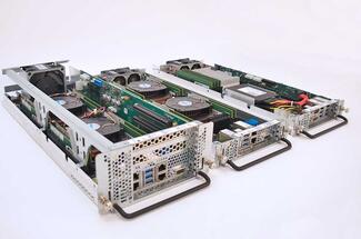
Secure, compact, scalable fixed, front-removable, or rear-removable blade servers made right here in the USA that maximize performance and adaptability for evolving applications
- Size - Up to four server blades within a single rugged enclosure help efficiently utilize rack space.
- Weight - Compact system design reduces overall weight of rack server infrastructure.
- Power - Shared resources optimize hardware usage and limit power requirements.
- Cost - Modularity and increased footprint lower hardware and maintenance costs.
Absolute EMC
Website
Absolute EMC LLC is a premier North American provider of electromagnetic compatibility (EMC) expertise and test equipment. They deliver end to end consulting—covering IEC, MIL STD, CISPR, and automotive standards—hands on training for all EMC and RF test instruments, and turnkey test system design and integration. Leveraging decades of experience with every major manufacturer and the latest technologies, they also offer strategic guidance on equipment selection, market trends, and procurement to help you maximize the performance and ROI of your EMC investments.